


方案详情
文
采用美国Artium公司无需光纤的集成了半导体泵浦固体激光器(DPSSL)的激光相位多普勒粒子干涉仪(PDI-100MD)对喷雾对象中的喷雾液滴粒子粒径和速度进行了实时测量和记录。这是一种表征喷雾特性的有效方法。
方案详情

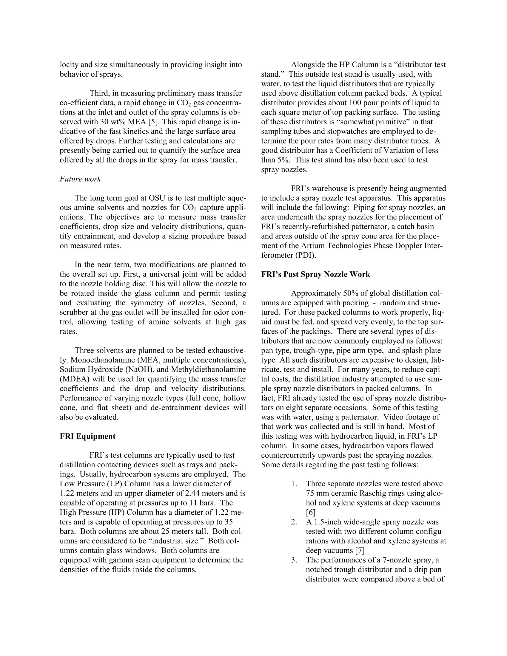
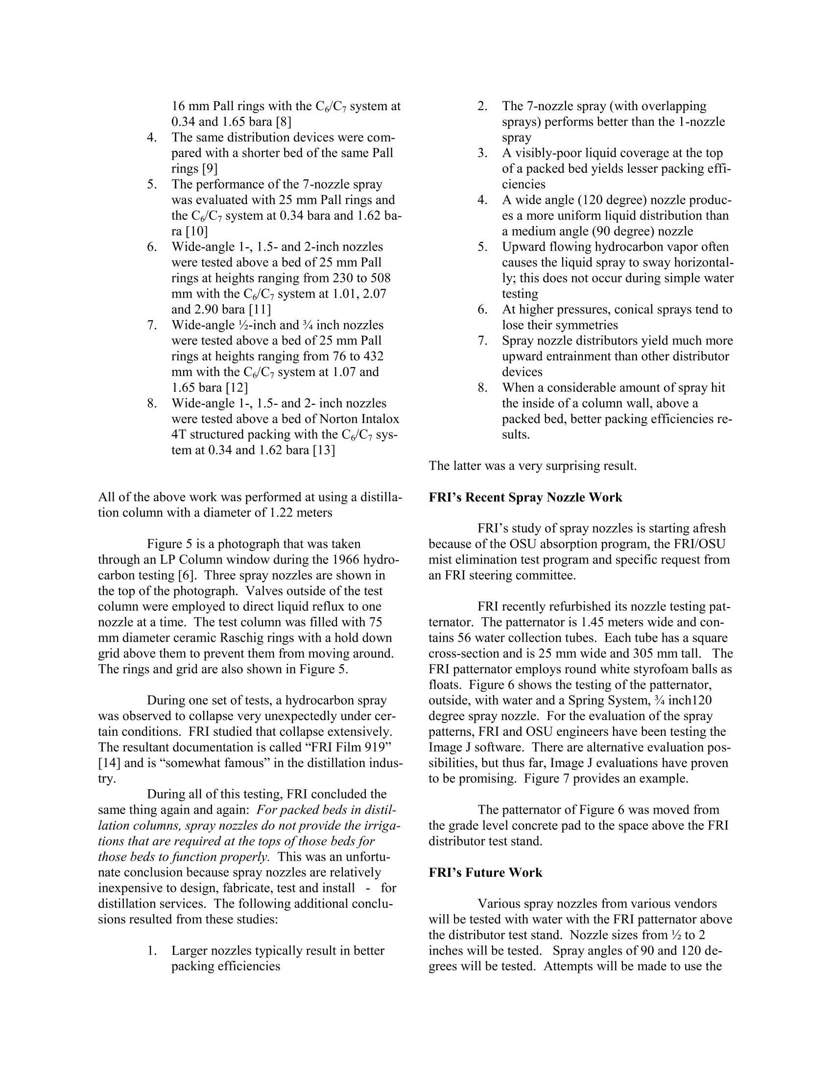
ILASS Americas 26th Annual Conference on Liquid Atomization and Spray Systems, Portland, OR, May 2014 Recent Advances in Spray Characterization at Laboratory and Industrial Scales Y. Tamhankar, B. King’, J. R. Whiteley, A.Y. Ogundeji, M.R. Resetarits2, T. J. Cai, S. Chambers. and C. P. Aichelel* School of Chemical Engineering Stillwater, OK 74078, USA Oklahoma State UniversityISA Fractionation Research Incorporated Stillwater, OK 74074, USA Abstract Refineries and chemical plants employ sprays in columns that often exceed 20 feet in diameter. Sprays are used totransfer heat, to feed beds of packing and to feed simple contacting trays. Very large nozzles are employed. Multi-nozzle sprays are employed. Very little is known about the actual performance of these spray nozzles in these hy-drocarbon and dirty hydrocarbon services. Several oil and chemical companies have convinced Fractionation Re-search Inc. (FRI) to review its 50-year history of spray nozzle research and to perform new research with water andalso with hydrocarbons in its 4-foot diameter windowed test columns. The FRI apparatuses are on the OklahomaState University (OSU) campus. For the last two years, OSU has been studying carbon dioxide removal from fluegases using spray columns. Carbon dioxide is a greenhouse gas, and many people believe that this gas is causingclimate change. Together, the FRI and OSU engineering staffs have embarked on a large spray nozzle test program.A patternator is being employed along with an Artium Technologies Phase Doppler Interferometer (PDI). This presentation will include film/video footage of spray nozzles functioning with hydrocarbon liquidsIS- and vapors. ( Corresponding author: clint.aichele@okstate.edu ) Fractionation Research Inc. (FRI) is a distilla-tion and absorption research facility that has the largestequipment in the world for such studies. FRI rentsspace on the Oklahoma State University (OSU) cam-pus. FRI engineers, OSU instructors, and OSU gradu-ate students collaborate regularly on topics like distilla-tion, absorption, process control, process safety, andmist elimination. OSU is currently working on a CO2absorption project that requires the fullest possible un-derstanding of spray nozzles. FRI and OSU are aboutto begin a laboratory study of mist elimination devices;this project will also require the use of such nozzles.Very recently, members of one of FRI’s steering com-mittees requested that the FRI staff readdress spraynozzle research work. FRI and OSU personnel are col-laborating again. Oklahoma State University -Spray nozzle testing Background The School of Chemical Engineering at OklahomaState University (OSU) has been testing spray nozzlesfor CO2 capture applications for the last two years. Theabsorption-stripping process with aqueous amine sol-vents, practiced for more than 80 years in natural gastreating [1], has been proposed for capturing CO2 frompost combustion sources such as flue gas from powerplants [2]. The low gas phase pressure drop [3] and lackof internals inside spray columns, making them lesssusceptible to corrosive amine solvents, were the twoprimary reasons which motivated the direction of re-search. Currently, there is a scarcity of reliable sprayCO2 absorption data. Further, there is no data on thedropsize distribution for amine solvents produced bycommercially available atomization nozzles. In order to address this gap, a lab-scale spray ab-sorption test facility has been constructed. The sprayabsorption measurements are augmented with drop sizeand velocity measurements using a Phase Doppler In-terferometer (PDI). The following section provides abrief description ofthis test facility. Lab apparatus The overall experimental spray setup at OSU,shown in Figure 1, consists of an 8-inch spray column,16 gallon feed and sump tanks, centrifugal feed pump,air blower, CO2 cylinder bank with a semi-automaticmanifold, Co2 mass flow meter, and gas chromato-graph for CO2 gas composition analysis. The gas chro-matograph is complimented with an infrared analyzerfor liquid composition analysis (not seen in Figure 1). The 8-inch spray column, shown in Figure 2, ismade of nine, 1-foot,borosilicate (QVF) glass sectionsand additional cylindrical top and bottom sections.Cus-tom insert plates are placed between two glass sections,and permit withdrawal of gas samples for compositionanalysis across the height of the column. The nozzle iscentered inside the column using a nozzle holding disc.A custom eye-piece insert permits PDI measurementsthrough dense wall on the inner wall of the glass col-umn. The location of the probe volume or the meas-urement point inside the spray is calculated based ontriangulation. Gas is injected at the bottom of the col-umn through a glass tee. A chimney tray at the gas inletdistributes the incoming gas uniformly and minimizesthe gas-liquid contact. Additional details of the eye-piece and column setup can be found elsewhere [4]. A 1-dimensional Phase Doppler Interferometer(100-MD,Artium Technologies), mounted on a manualtwo direction rail system (seen in Figure 2) is used tomeasure drop size and velocities across the sprayplume. The solvent from the feed tank are pumped to thenozzle by means of a centrifugal pump through a varia-ble area flow meter. This feed pump is rated for deliver-ing 16.1 gpm of water at 80 psig pressure. Two variablearea flow meters are used depending on the range ofliquid flow rates (0.1 -0.5 gpm and 1-10 gpm) tested.The gas is supplied counter-currently to the column bymeans of a centrifugal blower. The blower can deliverair at a maximum rate of around 400 ft’/min. This ratecorresponds to a gas velocity of around 10 ft/s insidethe glass column. The liquid and gas flow rates to thecolumn are controlled using variable frequency driveson the feed pump, and the blower, respectively. Key findings Three key findings have emerged from all thetests conducted so far. First, the nature of the diameterhistogram and the value of the Sauter mean diameterchange with the axial and radial locations inside thespray plume. Figure 3 shows the variation of the Sautermean diameter with the radial and axial locations for ahollow cone nozzle. Second, secondary effects are observed for allliquid and gas flow conditions, even without current gasflow. Figure 4 shows the velocity histogram and varia-tion of drop size against velocity plot for a full conenozzle, without any counter current gas flow. A largenumber of drops travelling with negative velocitiesaway from the spray center and outside of the sprayplume, indicates presence of secondary re-circulation.Figure 4 also exhibits the utility in measuring drop ve- locity and size simultaneously in providing insight intobehavior of sprays. Third, in measuring preliminary mass transferco-efficient data, a rapid change in CO2 gas concentra-tions at the inlet and outlet of the spray columns is ob-served with 30 wt% MEA [5]. This rapid change is in-dicative of the fast kinetics and the large surface areaoffered by drops. Further testing and calculations arepresently being carried out to quantify the surface areaoffered by all the drops in the spray for mass transfer. Future work The long term goal at OSU is to test multiple aque-ous amine solvents and nozzles for CO2 capture appli-cations. The objectives are to measure mass transfercoefficients, drop size and velocity distributions, quan-tify entrainment, and develop a sizing procedure basedon measured rates. In the near term, two modifications are planned tothe overall set up. First, a universal joint will be addedto the nozzle holding disc. This will allow the nozzle tobe rotated inside the glass column and permit testingand evaluating the symmetry of nozzles. Second, ascrubber at the gas outlet will be installed for odor con-trol, allowing testing of amine solvents at high gasrates. Three solvents are planned to be tested exhaustive-ly. Monoethanolamine (MEA, multiple concentrations),Sodium Hydroxide (NaOH), and Methyldiethanolamine(MDEA) will be used for quantifying the mass transfercoefficients and the drop and velocity distributions.Performance of varying nozzle types (full cone, hollowcone, and flat sheet) and de-entrainment devices willalso be evaluated. FRIEquipment FRI’s test columns are typically used to testdistillation contacting devices such as trays and pack-ings. Usually, hydrocarbon systems are employed. TheLow Pressure(LP) Column has a lower diameter of1.22 meters and an upper diameter of 2.44 meters and iscapable of operating at pressures up to 11 bara. TheHigh Pressure (HP) Column has a diameter of 1.22 me-ters and is capable of operating at pressures up to 35bara. Both columns are about 25 meters tall. Both col-umns are considered to be“industrial size.”Both col-一umns contain glass windows. Both columns areequipped with gamma scan equipment to determine thedensities of the fluids inside the columns. Alongside the HP Column is a“distributor teststand.” This outside test stand is usually used, withwater, to test the liquid distributors that are typicallyused above distillation column packed beds. A typicaldistributor provides about 100 pour points of liquid toeach square meter of top packing surface. The testingof these distributors is“somewhat primitive”in thatsampling tubes and stopwatches are employed to de-termine the pour rates from many distributor tubes. Agood distributor has a Coefficient of Variation of lessthan 5%. This test stand has also been used to testspray nozzles. FRI’s warehouse is presently being augmentedto include a spray nozzle test apparatus. This apparatuswill include the following: Piping for spray nozzles, anarea underneath the spray nozzles for the placement ofFRI’s recently-refurbished patternator, a catch basinand areas outside of the spray cone area for the place-ment of the Artium Technologies Phase Doppler Inter-ferometer (PDI). FRI’s Past Spray Nozzle Work Approximately 50% of global distillation col-umns are equipped with packing- random and struc-tured. For these packed columns to work properly, liq-uid must be fed, and spread very evenly, to the top sur-faces of the packings. There are several types of dis-tributors that are now commonly employed as follows:pan type, trough-type, pipe arm type, and splash platetype All such distributors are expensive to design, fab-ricate, test and install. For many years, to reduce capi-tal costs, the distillation industry attempted to use sim-ple spray nozzle distributors in packed columns. Infact, FRI already tested the use of spray nozzle distribu-tors on eight separate occasions. Some of this testingwas with water, using a patternator. Video footage ofthat work was collected and is still in hand. Most ofthis testing was with hydrocarbon liquid, in FRI’s LPcolumn. In some cases, hydrocarbon vapors flowedcountercurrently upwards past the spraying nozzles.Some details regarding the past testing follows: 1. Three separate nozzles were tested above75 mm ceramic Raschig rings using alco-hol and xylene systems at deep vacuums[6] 2. A 1.5-inch wide-angle spray nozzle wastested with two different column configu-rations with alcohol and xylene systems atdeep vacuums [7] 3. The performances of a 7-nozzle spray, anotched trough distributor and a drip pandistributor were compared above a bed of 16 mm Pall rings with the C6/C7 system at0.34 and 1.65 bara [8] 4. The same distribution devices were com-pared with a shorter bed of the same Pallrings [9] 5. The performance of the 7-nozzle spraywas evaluated with 25 mm Pall rings andthe C6/C7 system at 0.34 bara and 1.62 ba-ra [10] 6. Wide-angle 1-, 1.5- and 2-inch nozzleswere tested above a bed of 25 mm Pallrings at heights ranging from 230 to 508mm with the C6/C system at 1.01, 2.07and 2.90 bara [11] 7. Wide-angle %-inch and %4 inch nozzleswere tested above a bed of 25 mm Pallrings at heights ranging from 76 to 432mm with the C6/C7 system at 1.07 and1.65 bara [12] 8. Wide-angle 1-, 1.5-and 2- inch nozzleswere tested above a bed of Norton Intalox4T structured packing with the C6/C7 sys-tem at 0.34 and 1.62 bara[13] All of the above work was performed at using a distilla-tion column with a diameter of 1.22 meters Figure 5 is a photograph that was taken through an LP Column window during the 1966 hydro-carbon testing [6]. Three spray nozzles are shown inthe top of the photograph. Valves outside of the testcolumn were employed to direct liquid reflux to onenozzle at a time. The test column was filled with 75mm diameter ceramic Raschig rings with a hold downgrid above them to prevent them from moving around.The rings and grid are also shown in Figure 5. During one set of tests, a hydrocarbon spraywas observed to collapse very unexpectedly under cer-tain conditions. FRI studied that collapse extensively.The resultant documentation is called“FRI Film 919”[14] and is“somewhat famous”in the distillation indus-try. During all of this testing, FRI concluded thesame thing again and again: For packed beds in distil-lation columns, spray nozzles do not provide the irriga-tions that are required at the tops of those beds forthose beds to function properly. This was an unfortu-nate conclusion because spray nozzles are relativelyinexpensive to design, fabricate, test and install - fordistillation services. The following additional conclu-sions resulted from these studies: 1.Larger nozzles typically result in betterpacking efficiencies 2. The 7-nozzle spray (with overlappingsprays) performs better than the 1-nozzlespray 3. A visibly-poor liquid coverage at the topof a packed bed yields lesser packing effi-ciencies 4. A wide angle (120 degree) nozzle produc-es a more uniform liquid distribution thana medium angle (90 degree) nozzle 5. Upward flowing hydrocarbon vapor oftencauses the liquid spray to sway horizontal-ly; this does not occur during simple watertesting 6. At higher pressures, conical sprays tend tolose their symmetries 7. Spray nozzle distributors yield much moreupward entrainment than other distributordevices 8. When a considerable amount of spray hitthe inside of a column wall, above apacked bed, better packing efficiencies re-sults. The latter was a very surprising result. FRI’s Recent Spray Nozzle Work FRI’s study of spray nozzles is starting afreshbecause of the OSU absorption program, the FRI/OSUmist elimination test program and specific request froman FRI steering committee. FRI recently refurbished its nozzle testing pat-ternator. The patternator is 1.45 meters wide and con-tains 56 water collection tubes. Each tube has a squarecross-section and is 25 mm wide and 305 mm tall. TheFRI patternator employs round white styrofoam balls asfloats. Figure 6 shows the testing of the patternator,outside, with water and a Spring System, 34 inch120degree spray nozzle. For the evaluation of the spraypatterns, FRI and OSU engineers have been testing theImage J software. There are alternative evaluation pos-sibilities, but thus far, Image J evaluations have provento be promising. Figure 7 provides an example. The patternator of Figure 6 was moved fromthe grade level concrete pad to the space above the FRIdistributor test stand. FRI’s Future Work Various spray nozzles from various vendorswill be tested with water with the FRI patternator abovethe distributor test stand. Nozzle sizes from to 2inches will be tested. Spray angles of 90 and 120 de-grees will be tested. Attempts will be made to use the Artium PDI at the same time as the patternator,butspace limitations near the FRI liquid distributor teststand might prove to be preclusive. In response, a newapparatus is being assembled in FRI’s warehouse sothat spray nozzle testing can be performed there withthe patternator and the PDI being employed simultane-ously. Data from the new warehouse apparatus is cer-tainly expected in 2014. In 2015, it is expected that the FRI hydrocar-bon test columns will be available for another round ofspray nozzle testing. Figure 8 shows one possible testconfiguration. A long pipe would bring reflux liquiddown into a test column. This reflux liquid would passthrough a spray nozzle. A hydrocarbon vapor streamwould flow upwards countercurrent to the spray. Col-umn windows beneath that nozzle would allow for vis-ual observations and for PDI evaluations of dropletsizes, droplet velocities and droplet surface areas. ThePDI would then be moved to the higher windows andtotal evaluations of the entrained droplets would beeffected. During all of these tests, gamma scans of thecolumn would yield information regarding total fluiddensities. These density data could be used to evaluateliquid and vapor mass fractions at various heights insidethe column. Summary Over the last two years, FRI's global member-ship has expressed an extreme interest in spray nozzleresearch work, especially with large spray nozzles. Atthe same time, global governments, environmentalists,universities and global companies have expressed ex-treme interests in the removal of CO2 from flue gases.The economics of that removal depends strongly uponthe pressure drops of the absorption devices. OSU isstudying spray columns for the minimization of thosepressure drops. FRI engineers and OSU engineers areworking together synergistically to review applicablepast spray nozzle research work and to perform appli-cable beneficial new research work. Acknowledgements The authors of this paper acknowledge the ini-tiators ofFRI’s new round of spray nozzle testing: Mr.Greg Cantley of Marathon Petroleum, Mr. Todd Marutof ExxonMobil and Mr. Waldo deVilliers of Shell Oil.The authors also acknowledge the contributions of Mr.Dave William of FRI as well as the entire FRI techni-cian staff. 1. Kohl, A. L., Gas Purification, Gulf PublishingCompany, 1997,p. 41. 2.lRochelle, G.T.,Sciencee325(5948): 1652-1654(2009). 3.M1ehta, K. and M. Sharma, British Chemical Engi-neering 15(11):1440-1558. 4.Tamhankar, Y. S., J. R. Whiteley, M. R. Resetaritsand Aichele, C.P., Atomization and Sprays 24(2):115-128. 5.7Tamhankar, Y., Whiteley, J.R., Resetarits, M.R.,and Aichele, C.P., AIChE Annual Meeting, SanFrancisco, USA, November 2013. ( 6. Silvey, F.C. , FRI Progress Report November 1966. ) 7. Silvey, F.C., FRI Progress Report June 1967. 8. Yanagi, T. and Lahm, L., FRI Progress Report Jul-Aug 1982. ( 9 . Y anagi, T., Lahm, L . and Schweiger, F RI P rogress Report Sep-Oct 1982. ) ( 10. Yanagi,T. and Schweiger, C., FRI Progress ReportJan-Feb 1983. ) ( 1 1. L ahm, L. and Yanagi,T., FRI P r ogress ReportMay-Jun 1985. ) ( 12. Yanagi, T. and Lahm, L., F R I Progress Report Jul-Aug 1985. ) ( 13. C hambers, S., Fitz, C.W., C ai, T . J. and King,D.W., “H eat and Mass Transfer Performance o f Large Structured Packing (Short B ed), F RI ProgressReport Mar-Apr 1 997. ) ( 14. FRI staff, “Spray Collapse Study,”FRI F i lm 919. ) Figure 1.OSU experimental set up Figure 2. 8-inch spray column with salient features. Figure 3. Radial and axial variation of Sauter mean diameter inside a spray plume; test fluid - water; liquid rate-0.35 gpm; gas rate - 4.5 ft/s; hollow cone - Spraying Systems UniJet 44 TT-SS-D3-46-HSS. Velocity (m/s) Diameter (microns) Figure 4. Secondary effects away from the spray center; test fluid - water; liquid rate- 0.26 gpm; gas rate -0 ft/s;full cone -BETE MaxiPass 1/8 MPL 0.30N. Figure 5. Spray nozzles above packed bed in hydrocarbon column. Figure 6. Testing of refurbished FRI patternator. Figure 7. Image J analysis of patternator photograph. Figure 8. Spray nozzle testing in hydrocarbon column with PDI. Refineries and chemical plants employ sprays in columns that often exceed 20 feet in diameter. Sprays are used to transfer heat, to feed beds of packing and to feed simple contacting trays. Very large nozzles are employed. Multi-nozzle sprays are employed. Very little is known about the actual performance of these spray nozzles in these hy-drocarbon and dirty hydrocarbon services. Several oil and chemical companies have convinced Fractionation Re-search Inc. (FRI) to review its 50-year history of spray nozzle research and to perform new research with water and also with hydrocarbons in its 4-foot diameter windowed test columns. The FRI apparatuses are on the Oklahoma State University (OSU) campus. For the last two years, OSU has been studying carbon dioxide removal from flue gases using spray columns. Carbon dioxide is a greenhouse gas, and many people believe that this gas is causing climate change. Together, the FRI and OSU engineering staffs have embarked on a large spray nozzle test program. A patternator is being employed along with an Artium Technologies Phase Doppler Interferometer (PDI). This presentation will include film/video footage of spray nozzles functioning with hydrocarbon liquids - and vapors.*Corresponding
确定


还剩6页未读,是否继续阅读?

产品配置单


北京欧兰科技发展有限公司为您提供《喷雾中液滴粒径和速度检测方案(激光干涉仪)》,该方案主要用于其他中液滴粒径和速度检测,参考标准--,《喷雾中液滴粒径和速度检测方案(激光干涉仪)》用到的仪器有激光相位多普勒干涉仪LDV,PDI,PDPA,PDA、LaVision SprayMaster 喷雾成像测量系统
相关方案
更多
该厂商其他方案
更多