


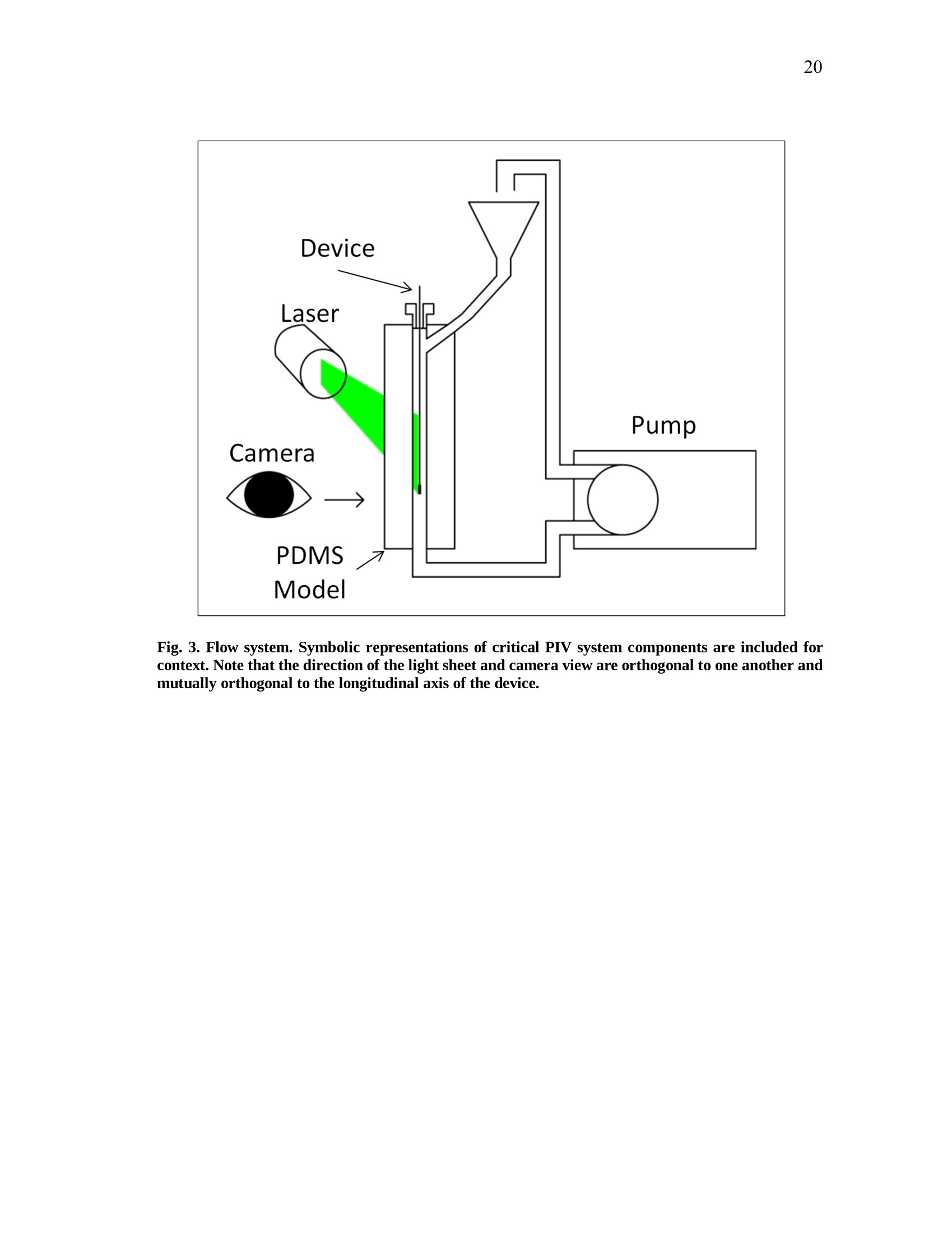
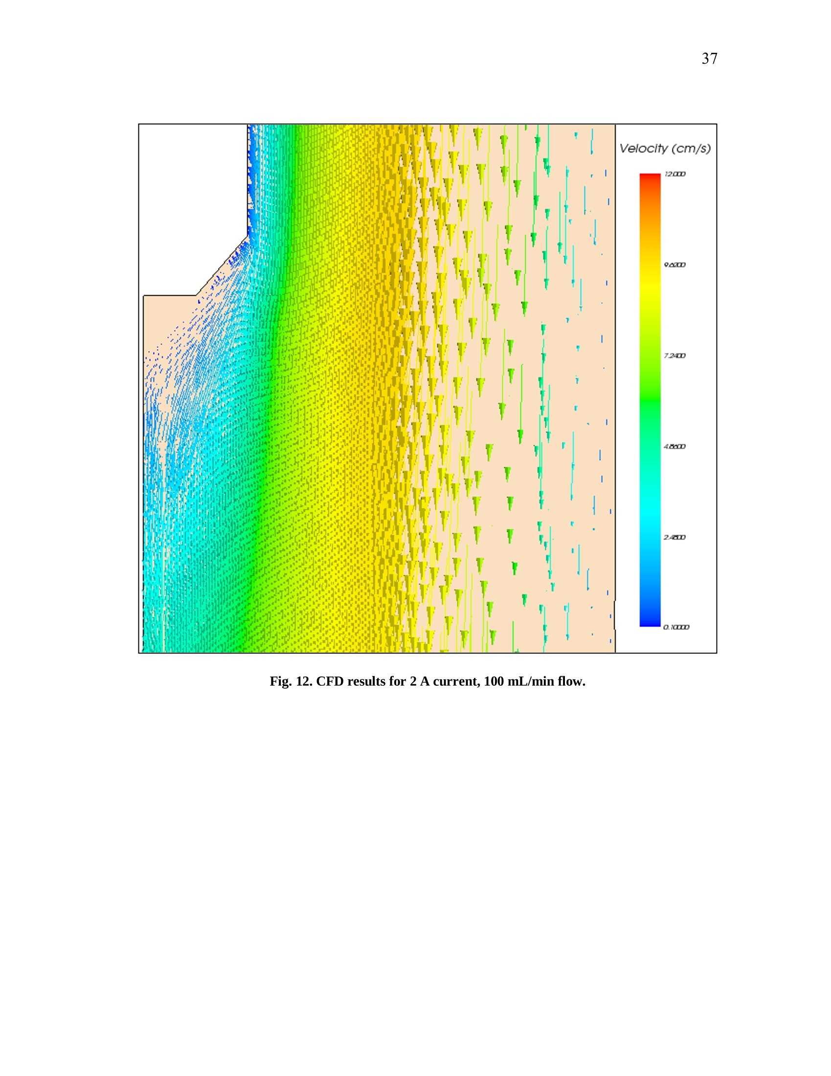
Shape memory polymer foams may be used to treat vascular aneurysms through thermal actuation of the foam from a compacted to an expanded configuration within the aneurysm structure, thereby alleviating blood pressure on the weakened aneurysm walls and reducing potential for rupture. After delivery to the aneurysm site, fiber-delivered laser light absorbed by the foam structure is converted into thermal energy, and actuation of the foam results. Introduction of nonphysiological energy into the body during foam actuation necessitates an evaluation of potential thermal damage to nearby tissue.
In the present investigation, the foam is idealized as a heat-dissipating, volumetrically static object centered in a straight tube of flowing water. Velocity profiles around the heat-dissipating device are acquired experimentally with particle image velocimetry. A computational fluid dynamics package is then used to predict the experimental velocity profiles and temperature distributions by numerical solution of the Navier-Stokes and energy equations, and agreement between the computational solution and experimental results is assessed. Discussion of this assessment, as well as several preliminary procedures leading up to the creation of the heat-dissipating device and critical analysis of the methods employed, is also given. PIV and CFD are found to be in reasonable agreement with one another. Using laser-induced fluorescence as a temperature measurement modality, which is discussed in the text insofar as the technique was attempted several times and failed, together with PIV and CFD provides a formidable array of techniques exists to characterize flow around a heated device.
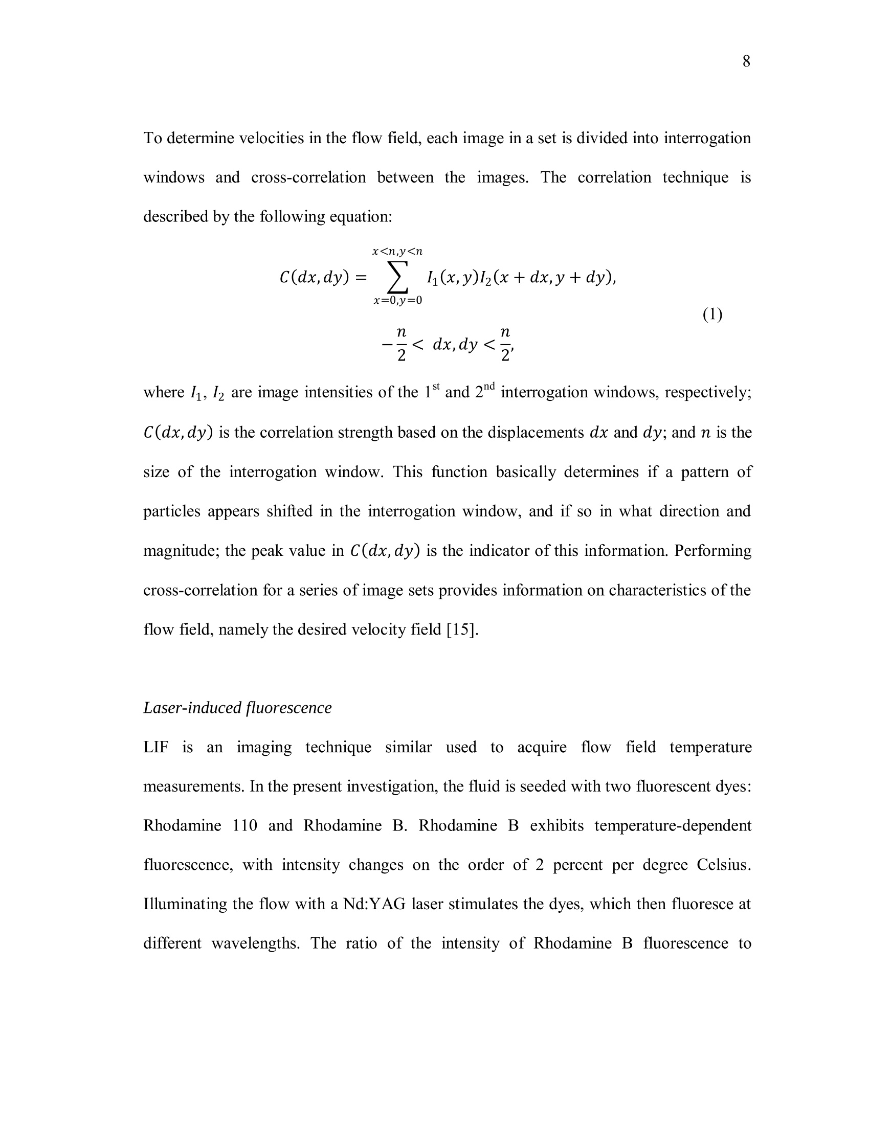
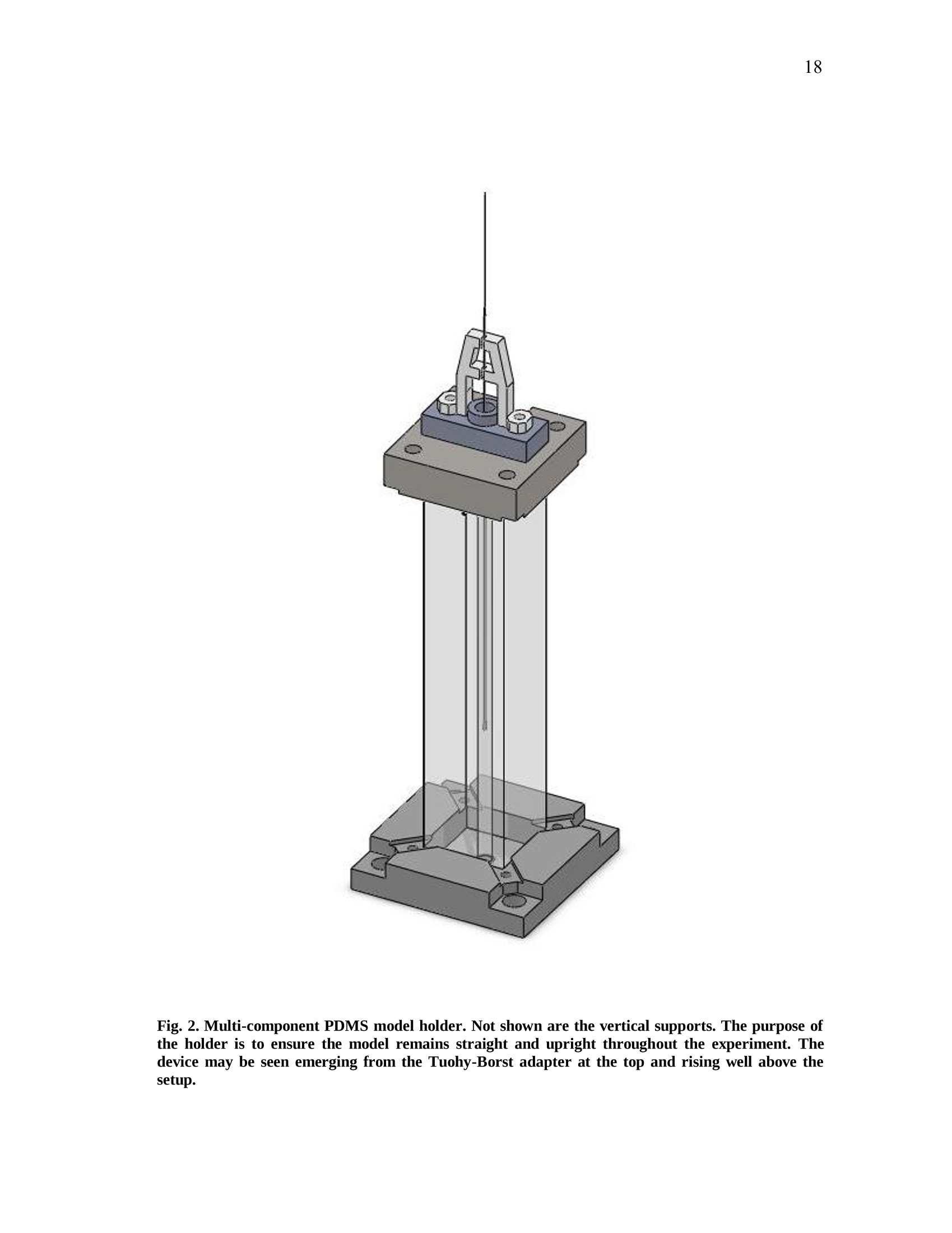
方案详情

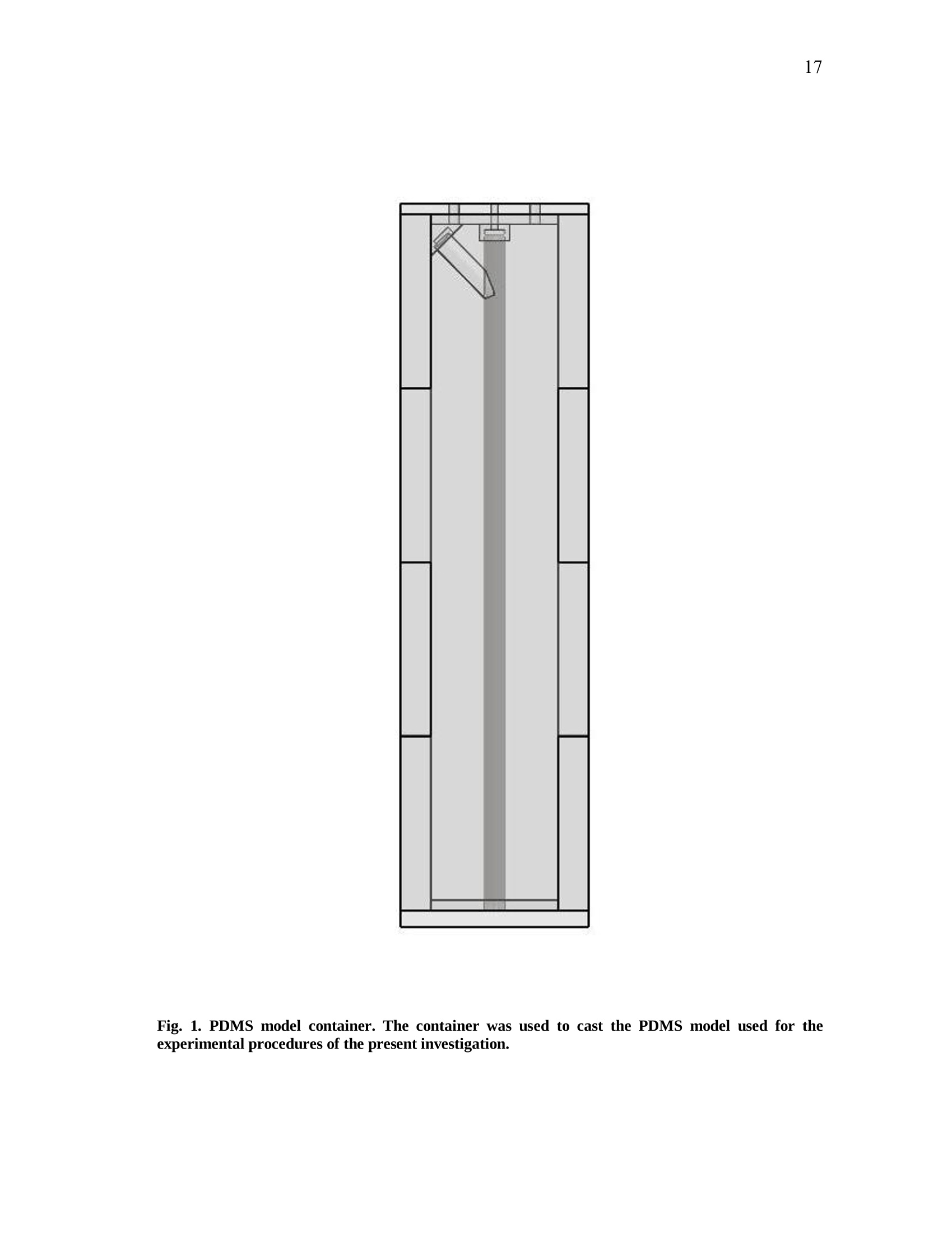
iii iv COMPUTATIONAL AND EXPERIMENTAL EVALUATIONOFACTUATING SHAPE MEMORY POLYMER FOAMS IN THE CONTEXT OF ANEURYSM TREATMENT An Honors Fellows Thesisby EDWARD KARL HAHN III Submitted to the Honors Programs Office Texas A&MUniversity in partial fulfillment of the requirements for the designation as HONORS UNDERGRADUATE RESEARCH FELLOW April 2010 Major: Biomedical Engineering COMPUTATIONAL AND EXPERIMENTAL EVALUATIONOFACTUATING SHAPE MEMORY POLYMER FOAMSIN THE CONTEXT OF ANEURYSM TREATMENT An Honors Fellows Thesis by EDWARD KARL HAHN III Submitted to the Honors Programs OfficeTexas A&M Universityin partial fulfillment of the requirements for the designation as HONORS UNDERGRADUATE RESEARCH FELLOW Approved by: Research Advisor: Duncan J. MaitlandAssociate Director of the Honors Programs Office: Dave A. Louis April 2010 Major: Biomedical Engineering ABSTRACT Computational and Experimental Evaluation of Actuating Shape Memory PolymerFoams in the Context of Aneurysm Treatment. (April 2010) Edward Karl Hahn IIIDepartment of Biomedical EngineeringTexas A&M University Research Advisor: Dr. Duncan J.MaitlandDepartment of Biomedical Engineering Shape memory polymer foams may be used to treat vascular aneurysms through thermalactuation of the foam from a compacted to an expanded configuration within theaneurysm structure, thereby alleviating blood pressure on the weakened aneurysm wallsand reducing potential for rupture. After delivery to the aneurysm site, fiber-deliveredlaser light absorbed by the foam structure is converted into thermal energy, and actuationof the foam results. Introduction of nonphysiological energy into the body during foamactuation necessitates an evaluation of potential thermal damage to nearby tissue. In the present investigation, the foam is idealized as a heat-dissipating, volumetricallystatic object centered in a straight tube of flowing water. Velocity profiles around theheat-dissipating device are acquired experimentally with particle image velocimetry. Acomputational fluid dynamics package is then used to predict the experimental velocityprofiles and temperature distributions by numerical solution of the Navier-Stokes andenergy equations, and agreement between the computational solution and experimental esults is assessed. Discussion of this assessment, as well as several preliminaryprocedures leading up to the creation of the heat-dissipating device and critical analysisof the methods employed, is also given. PIV and CFD are found to be in reasonableagreemenitt wyith one another. Using laser-induced fluorescenceas atemperaturemeasurement modality, which is discussed in the text insofar as the technique wasattempted several times and failed, together with PIV and CFD provides a formidablearray of techniques exists to characterize flow around a heated device. DEDICATION If the work I have performed is somehow worthy of giving to another, I freely give it tomy heavenly Father Who continuously bestows upon me blessing after blessing when Iam deserving of much less. Thank You, Father, for the love You have shown me in YourSon and in my short but lengthening journey through this life You have given me. ToYou alone be the glory. ACKNOWLEDGMENTS I owe a debt of gratitude to my parents for their unwavering support and encouragement,but most of all their love. I cannot ask for better. Thank you. Thanks also to Mr. Howard Terry for graciously funding the college education of a kidfrom Georgetown, TX whom you had never met before. I believe your investment hasnot been wasted. Thank you. I also wish to acknowledge Dr. Duncan Maitland for allowing an overambitiousundergraduate to think and act like a graduate student and for freely setting before meopportunities unheard of elsewhere. Thank you. Thanks also to the Biomedical Device Laboratory group, specifically Wonjun Hwangand Jennifer Rodriguez, for patient assistance, advice, and hours of conversation aboutthe lab and life. Thank you. Finally, I wish to acknowledge NIH/NIBIB Grant R01EB000462 and the Texas A&MUniversity Honors Program for funding used to support this work. NOMENCLATURE CFDComputational Fluid DynamicsLIFLaser-induced FluorescencePIVParticle Image VelocimetrySMPShape Memory Polymer TABLE OF CONTENTS Page ABSTRACT. iii DEDICATION. ACKNOWLEDGMENTS. vi NOMENCLATURE . vii TABLE OF CONTENTS. .viii LIST OF FIGURES .X CHAPTER .INTRODUCTION. 1 Motivation.... 1 Scope of the thesis. 2 II BACKGROUND AND OBJECTIVE. 4 Techniques. Aneurysms. 47 Objective.. 10 LITERATURE REVIEW. 11 Computational fluid dynamics. Particle image velocimetry.mma Laser-induced fluorescence.. B . Techniques in combination..... IV METHODS.. .... 15 Philosophical approach..... Experimental methods design... Computational methods.. CH A P T E R Page V RESULTS AND DISCUSSION. 28 Power versus current .... Calorimetry...... PIV and CFD 2 3 LIF. 3 VI SUMMARY AND CONCLUSIONS. 40 REFERENCES. 42 CONTACTINFORMATION. 46 LIST OF FIGURES .FIGURE Page 1 PDMS model container ..... .117 2 Multi-component PDMS model holder.. .18 3 Flow system.... .20 4 .Cross-sectional schematic of heat-dissipating device . .22 5 Image of the actual device. 23 65(Computational model of the heat-dissipating device. 23 / Power versus current relationship for UM7800. .28 8 PIV results for 0 A current, 100 mL/min flow.. .33 9 PIV results for 2 A current, 100 mL/min flow...... .34 10 PIV results for 3 A current, 100 mL/min flow.. .35 11 CFD results for 0 A current, 100 mL/min flow/. .36 12 CFD results for 2 A current, 100 mL/min flow.. .37 13 CFD results for 3 A current, 100 mL/min flowV. .338 CHAPTERIINTRODUCTION Motivation In the science of medical device design there is a need for accurate computationalmodelingandd correspondingexperimentalvalidation of device characteristics.Experimentally verified computational models provide a means of predicting deviceperformance and failure in the body. The goal of the present work is to evaluate theagreement between two analogous experimental and computational approaches to flowvelocity and temperature field characterization in the context of an academic formulationof shape memory polymer foam actuation within an aneurysm. Particle image velocimetry (PIV) and laser-induced fluorescence (LIF) techniques areemployed with the intent of quantitatively measuring the velocity and temperature fields,respectively, around an idealized shape memory polymer foam device undergoingactuation. The PIV technique elucidates flow velocities by seeding the flow field withtracer particles and imaging the tracer particles at two successive instants with a knownintervening time increment. The two images are analyzed using the cross-correlationstatistical technique to determine the direction of all particle displacements in the flow ( This thesis follows the style of IEEE Transactions on Biomedical Engineering. ) field. In a similar manner, the LIF technique seeds a flow with two fluorescent dyes,exactly one of which possesses temperature-dependent fluorescent intensity. Flow fieldimaging is according to the fluorescent intensities of the dyes, which are compared to acalibration standard to determine fluid temperature. Taken together, the PIV and LIFtechniques empirically determine velocity and temperature fields within a flow field atdiscrete points. The computational fluid dynamics (CFD) technique is the computational analogue of thePIV and LIF techniques. An experimental flow field is modeled using a computer-aideddesign package and discretized into volumetric elements, and the governing equationsare solved iteratively to convergence for each element.Velocity and temperatureinformation are extracted from the volumetric elements, yielding the computationalanalogue of the experimental PIV and LIF results and enabling quantitative comparisonsbetween the empirical data and theoretical expectations. Scope of thesis An evaluation of the agreement between experimental (PIV) and computational (CFD)techniques for flow field characterization, specifically the associated velocity field, isprovided in the following chapters. LIF is discussed insofar as the experimentalprocedure and potential improvements to gain accurate results, but reportable resultswere not acquired and are not presented. Chapter II provides necessary context to the present investigation. Relevant backgroundonnaneurysm and shape memory polymersiss given, and the experimental :il andcomputational techniques employed are explained in detail. Chapter II closes with aprecise statement of the problem addressed in this work. A review of the literature is given in Chapter III and is used to demonstrate the dearth ofinformationconcerningmedicaldevicceharacterizationutilizingexperimentaltechniques such as PIV and LIF. Chapter IV describes the methodsfollowed in thiswork. An overview of thephilosophical approach taken to formulation of the problem statement into experiment isprovided. The steps taken for both the experimental and computational approaches aredescribed in detail. Chapter V presents the experimental and computational results obtained from themethods described in Chapter IV. The chapter closes with a discussion of the results.This discussion includes detailed comparisons of the results, and analysis of theagreement between the experimentally and computationally obtained velocity andtemperature fields. Finally, a summary of the present work and the primary conclusions are given in ChapterVI. CHAPTERIBACKGROUND AND OBJECTIVE Aneurysms An aneurysm is a cardiovascular disease characterized by evolution of a weakening ofthe arterial wall into a balloon-like structure susceptible to rupture. The disease processassociated with rupture of cerebral aneurysmss is thought to be mediated by theinteraction between hemodynamic forces and the arterial wall biology [1]. The rupture ofintracranialaneurysms accounts for 80 percentt(of nontraumaticsubarachnoidhemorrhage (SAH) cases. Nearly half of the survivors of SAH will be afflicted long-term cognitive impairment [2]. A number of hemodynamic characteristics have been implicated in the rupture ofsaccular aneurysms, including concentrated inflow jets with small impaction zones,elevated wall shear stress, and complex unstable flow patterns [3]. Indeed, unrupturedaneurysms tend to exhibit hemodynamics characterized by diffuse inflow jets, large flowimpingement regions, and simple stable flow patterns [4]. Because of the intimate rolethat hemodynamics appear to have in the rupture process of aneurysms, two currenttreatment methods seek to isolate the weakened wall of an aneurysm from high pressure,pulsating blood flow to prevent or treat rupture. Current treatments Neurosurgical clipping of the aneurysm developed first as the primary technique fortreatment of SAH and involves craniotomy to access the aneurysm in question. Studiesin the 1960s showed the benefits outweighed risks in circumstances of favorable locationof the aneurysm within the brain, and the risk of surgery has been progressively reducedthrough a variety of medical advances. Few patients, however, have been capable ofreturning to a normal lifestyle [5]. i1n 1990, the Guglielmi Detachable Coil (GDC) was iintroduced as an alternativetreatment modality for aneurysms [5-7]. GDC treatment promotes thrombus formationwithin the aneurysm structure. The device consists of a soft platinum coil soldered to astainless steel delivery wire and is delivered via endovascular approach. Specifically,treatment relies on the principals ofelectrothrombosis and electrolysis.Electrothrombosis results from the attraction of negatively charged blood components,such as red and white blood cells, to a positively charged electrode; thrombosis ispromoted by this process. Electrolysis of the solder enables intra-aneurysmal placementof the platinum coil [7]. Overall, the literature shows the GDC technique to be widelysuccessful compared to previous techniques [5, 8, 9], but since its inception, thetechnique has suffered from a number of deficiencies, including incomplete aneurysmocclusion [6], instability of coiling over time [10], inability to effectively treatment largeaneurysms [10, 11], and time-consuming surgery [12]. An alternative treatment modalityusing shape memory polymer (SMP) foam to fill aneurysms has been proposed and is currently in developmentby Lawrence LLiivveerrmmoorree National Laboratoryand theBiomedical Device Laboratory at Texas A&M University. Proposed treatment In general, SMPs form a class of so-called smart materials capable of mechanicalactuation from one configuration to another in response to a stimulus [13]. In the presentcase, the stimulus ofinterest is heat. Heating raises the temperature of the SMP foamabove its glass transition temperature, thereby decreasing the elastic modulus of thematerial and promoting foam expansion from the compressed state required for catheterdelivery to the full volume of the aneurysm. Advantages to SMP foam treatment willinclude endovascular treatment via catheter, faster treatment time, and 60-fold expansioncapabilities from the crimped state required for endovascular delivery [12]. Importantly,if the glass transition temperature of the SMP foam is above body temperature, anenergy source external to the body must be used to heat the foam in vivo to achieveactuation and filling of the aneurysm. The introduction of non-physiologic energy intothe body necessitates determination of potential thermal damage to blood andsurrounding tissue. Analysis of this problem as it pertains to a heat-dissipating device inthe body is the basis for the present inquiry. Techniques Particle image velocimetry PIV iss aa technique used to indirectly measure fluid velocity fields. It relies onmeasurement of tracer particle positions with known time increments between thepositions. Knowledge of both these parameters-particle positions and time betweenpositions-enables calculation of particle velocity. If the properties of the tracer particlesare not too different from the properties of the fluid, then the particle velocities are agood estimation of the fluid velocity [14]. In the present investigation, particle positions are acquired by 2 CCD cameras anddouble pulse illumination of the flow field around the heat-dissipating device beingstudied. Importantly, the illumination is provided in the form of a so-called light sheet,allowing for the approximation that the images acquired contain data from a plane. Thedouble pulse illumination is provided by a Nd:YAG laser, and the pulse sequence timingcorresponds to the exposure sequence of the CCD cameras. Each camera is exposedtwice per set of illuminating pulses,once for each pulse, giving 2 sets of2 images. Eachimage set meets the criteria described above. The two images in aaseatt ccontaininformation regarding particle position, and the time-lapse betweenlaser pulsesdetermines the separation of the particles in the image. To determine velocities in the flow field, each image in a set is divided into interrogationwindows and cross-correlation betweeenn tthhee iimmaaggees.s .The correlation technique isdescribed by the following equation: where l1, I2 are image intensities of the 1t and 2"d interrogation windows, respectively;C(dx,dy)is the correlation strength based on the displacements dx and dy; and n is thesize of the interrogation window. This function basically determines if a pattern ofparticles appears shifted in the interrogation window, and if so in what direction andmagnitude; the peak value in C(dx, dy) is the indicator of this information. Performingcross-correlation for a series of image sets provides information on characteristics of theflow field, namely the desired velocity field [15]. Laser-induced fluorescence LIFisan imaging technique similar usedtoacquire flowfield.itemperaturemeasurements. In the present investigation, the fluid is seeded with two fluorescent dyes:Rhodamine 110 and Rhodamine B. Rhodamine B exhibits temperature-dependentfluorescence, with intensity changes on the order of 2 percent per degree Celsius.Illuminating the flow with a Nd:YAG laser stimulates the dyes, which then fluoresce atdifferent wavelengths. The ratio of the intensity of Rhodamine B fluorescence to Rhodamine 110 fluorescence can be used in combination with a calibration to determinefluid temperature differences in a flow field. Computational fluid dynamics CFD is based on the continuum assumption: the equations that govern the whole alsogovern arbitrarily sized computational elementsSiiin the domain. The smaller thecomputational elements are, the better the resulting numerical approximation is to theactual solution of the governing equations—and presumably to reality. Three primarygoverning equations :are of interest in the present investigation: the continuity,momentum, and energy eqquuaattiioonnss.. When these equations are iteratively solved toconvergence for the computational elements of interest, velocity and temperatureinformation corresponding to flow of a certain fluid at the location of the computationalelement may be obtained. For the computational results too approximate reality as si closely as possible, thecomputational domain should also closely resemble reality. This criterion may beaccomplished by modeling the real experimental setup with a CAD package, thenmeshing the model to obtain the individual computational elements. The size and shapeof the computational elements is important to the speed with which the solver is able toconverge to a solution, as well as to the accuracy of the solution. Larger computationalelements will not be able to adequately resolve finer details in the flow, but many smaller elements will require significant computing time to arrive at a solution. Abalance between these two conditions is necessary. The choice of boundary conditions is also of critical importance. Replicating thedimensions of an experiment within a CAD package is relatively simple. Choosingboundary conditions that mimic real life is not as simple, and is a major challenge inobtaining accurate results. For this reason, several critical measurements are acquiredfrom the experimental setup in the present investigation that may be inputted into thecomputational model, namely inlet flow rate and internal temperature of the heat-dissipating device. Objective The goal of the present investigation is to utilize the experimental PIV and LIFtechniques in combination with CFD to attempt an analysis of fluid velocity andtemperature around a heat-dissipating device in a flow. The present investigation isessentially an analysis of the applicability of the above techniques to the problem ofcharacterizing actuating SMP foams. CHAPTERIILITERATURE REVIEW Computational fluid dynamics The literature shows significant breadth work in the field of cardiovascular fluidmechanics [16], and the use of both CFD and PIV is well-represented. A number ofstudies have employed CFD to aneurysm specific investigations, and the use of patient-specific computational geometries has proved useful [17]. Cebral et al. constructed 62patient-specific models of cerebral aneurysms from 3D angiographic data for thepurposes of CFD investigation [18, 19]. Simulated flow patterns within the aneurysmswere used as a basis for categorization of the aneurysm geometries. Flow within morethan 70 percent of the aneurysms that ruptured was characterized by at least one of thefollowing phenomena: complex or unstable flow patterns, small impingement regions,and small jet sizes. More than 73 percent of the unruptured aneurysms, however, weredescribed by simple, stable flow patterns, large impingement regions, and large jet sizes.Steinman et al. sought to correlate CFD-derived flow patterns to coil compaction [17].Hassan et al. utilized CFD to make recommendations on aneurysm treatment for aspecific patient, as well as to predict future aneurysm growth. Their prediction wasconfirmed with a follow-up examination 6 months later [20]. Shojima et al. used CFDresults to contend that wall shear stress may facilitate and trigger cerebral aneurysmrupture; wall shear stress is recommended as a metric for rupture prediction [21]. Castroet al.applied CFD to a variety of patient-specific aneurysms and critically assessed the usefulness of current methods of obtaining realistic geometries [22]. Ortega et al.analyzed post-treatment hemodynamics of a basilar aneurysm after theoretical treatmentwith SMP foam to determine the potential for harmful hemodynamic stresses.Simulations predicted elevated wall shear stresses that might result in remodeling of thearterial wall [231. CFD has also been applied to endovascular devices, such as stents, in the context ofaneurysms. Stuhne et al. applied computational methodologies to a stented saccularaneurysm geometry. Recommendations on computational mesh requirements were madeand analysis of wall shear stress distribution analyzed [24]. Radaellia et al. also analyzedstented aneurysms, but utilized patient-specific geometries for the analysis [25]. More relevantly, CFD simulations of an idealized heated SMP foam have beenperformed by Ortega et al. The foam was modeled as a sphere at discrete points in theactuation process, within a generic basilar aneurysm geometry. Notably, worst-casesimulations predicted 25 ℃ aneurysm wall temperature increases as a result of foamactuation. These temperature increases were consistently at the apex of the aneurysmgeometry, which exhibited the greatest isolation from convective cooling [26]. Particle image velocimetry PIV has also been employed in a number of investigations seeking to characterizeaneurysmal flow patterns. Yu et al. employed PIV to the investigation of abdominal aortic aneurysms. A variety of Reynolds and Womersley numbers were considered,specifically in analyzing recirculation zones within the aneurysm [27]. Tsai et al.considered the vascular dynamics of a saccular basilar aneurysm. A generic geometryidentical to the computational geometry employed by Ortega et al. was used, and overallagreement between the experimental results of Tsai et al. and the computational resultsof Ortega et al. was observed [28]. PIV has also been applied to flow around stents. Ionita et al. applied PIV to investigatethe effect of asymmetric stents on blood flow [29]. Laser-induced fluorescence LIF as a temperature measurement modality is not as well-represented as CFD or PIV inthe literature, but several investigations relevant to the present work were found. Hui etal. and Seuntiens et al.both considered heated cylinders in cross-flow using moleculartagging velocimetry and LIF, respectively. Good qualitative agreement is found betweenbothsets of results, affirming the usefulness of whole-field fluid tteenmperaturemeasurements using such techniques [30, 31]. Sakakibara et al. and Coolen et al. allperformed whole-field temperature measurements using Rhodamine dyes and found themeasurement error to be 1.7℃ and 0.1 K, respectively. It should be noted, however, thatthe range of temperature of the latter was only 0.7 K, whereas the former providesresults for 20-60℃[32,331. Techniques in combination Several notable investigations have combined 1 or more of the above techniques. Ford etal. compared PIV and CFD measurements in the same aneurysm geometry for thepurpose of CFD validation, an important requirement as the sophistication of CFDmodels increases [34]. Baranyi et al. combined PIV and two different CFD codes for theoses of analyzing cross-flowaaround aa hheatedcylinder. Their resultsshowqualitative agreement with Hui et al. and Seuntiens et al [35]. Finally, Babiker et al.combined PIV and CFD to predict hemodynamics in a generic basilar artery geometrysimilar to that of Ortega et al. and Tsai et al. Interestingly, they modeled the influencesof coil-packing density on flow dynamics, insofar as the coils affected flow in the parentvessels, but not within the aneurysm [36]. CHAPTERIVMETHODS Philosophical approach Computationally modeling an actuating SMP foam is not a trivial task. A variety issuesarise in this endeavor: the foam structure is porous and not easily modeled in a CADpackage; the shape and temperature of the foam structure are changing in time; and thein vivo flow conditions, blood clotting physics, and vascular anatomy are complex.These issues are not easily dealt with in the beginning of a series of experimentalinvestigations. Rather, it is instructive to future investigation to start with a simpleproblem-a so-called academic problem-and gradually complicate it to analyze theentire complex problem. To start with a simple problem, assumptions must be made in the present investigation.The complex geometry of the foam and vascular are neglected in favor of a solid,nonporous, heated metal-epoxy cap and a long, straight tube with fully developed flow.Additionally, all boundary conditionsare temporally static. The result of theseassumptions is a relatively simple computational model and correspondingly simpleexperimental setup. Experimental methods design PDMS model creation A mold container was machined piecewise from acrylic sheet using a CNC (Fig. 1). A 6mm diameter stainless steel rod served as the flow channel negative. Sufficient lengthwas allotted to allow for full development of the flow profile within the channel. A 6mm diameter angled inlet channel negative was machined from acrylic and held at a 45°to the flow channel negative. Aluminum adhesive tape was used to secure the pieces ofthe mold container. PDMS (Sylgard 184, Dow Corning) was poured into the mold andcured for 45 minutes at 80C. While the model was warm, the container sides andchannel negatives were removed. PDMS model holder To ensure that the PDMS model was held rigidly in front of the PIV microscope, amulti-component holder was devised (Fig. 2). The holder consisted of an ABS plasticbottom mount adapted to the PIV system optical railing, 4 acrylic vertical supports, 2 ofwhich were later replaced by 1/8 inch threaded rods to allow for vertical adjustments; anABS plastic top mount adapted to the top surface of the PDMS mold; and a two-partsupport system to hold the device centered within the flow channel that included a 3/8inch diameter vented cap screw and rubber pad to form a seal around the device in themanner of a Tuohy-Borst adapter. All components were held in place by 8-32 cap screwsand nuts. Fig. 1. PDMS model container. The container was used to cast the PDMS model used for theexperimental procedures of the present investigation. Fig. 2. Multi-component PDMS model holder. Not shown are the vertical supports. The purpose ofthe holder is to ensure the model remains straight and upright throughout the experiment. Thedevice may be seen emerging from the Tuohy-Borst adapter at the top and rising well above thesetup. Flow system A gravity-fed flow system (an elementary design of which is illustrated in Fig.3) wasconstructed from 1/4 inch inner diameter Tygon tubing (VWR Scientific). An elevatedreservoir was fed by a peristaltic pump drawing from a source reservoir. The elevatedconsisted of a funnel bound to a 1/4 inch tube adapter protruding through the bottom of aplastic beaker. An additional 1/4 inch tube adapter protruded through the bottom of thebeaker and served to allow overflow to return to the source reservoir. Reservoir heightswere controlled to manipulate flow rate, which was measured downstream of the deviceflow channel with an ultrasound flowmeter and probe (T206, Transonic Systems Inc.).To acquire downstream temperature measurements, 3 thermocouples (OMEGA) wereinserted through the PDMS model and into the center of the primary flow channel 6 mm,5 mm, and 6 mm from the position of the heat-dissipating device. Fig. 3. Flow system. Symbolic representations of critical PIV system components are included forcontext. Note that the direction of the light sheet and camera view are orthogonal to one another andmutually orthogonal to the longitudinal axis of the device. Heat-dissipating device The heat dissipating device used to model a SMP foam in the early stages of actuationwas formed from multiple components. A 200 um optical fiber (Polymicro Industries,LLC) was terminated in a thermally conductive epoxy (H70E-2, Epo-Tek) containedwithin a metal cap with a 0.150 inch deep, 0.035 inch inner diameter hold machinedfrom a 4 mm long, 0.052 inch outer diameter stainless steel 17-4 PH rod (Small Parts,Inc.). The fiber was approximately concentric with the metal cap and inserted about0.120 inches into the thermally conductive epoxy. Additionally, the junction of a 0.003inch T-type thermocouple (OMEGA) was terminated in the thermally conductive epoxyat the maximal depth to the side of the optical fiber. The thermally conductive epoxywas then cured for 20 minutes at 100°℃ and 1 hour at 150 ℃. At this point, calorimetricexperiments were performed; see Calorimetry. The optical fiber and one thermocouplelead were bundled together in a Teflon sheath to insulate the thermocouple leads fromone another. The bundle and the unsheathed thermocouple lead were drawn through a0.042 inch outer diameter, 0.032 inch inner diameter stainless steel 304 tube (SmallParts, Inc.). This catheter-like tube served to support the heat-dissipating metal cap in thefluid flow. The metal cap and supporting tube were epoxied together with a thermallyinsulating epoxy (Blue-Dye Epoxy, FIS). Fig. 4 provides a graphical summary of thecomponents of the heat-dissipating device. Fig. 5 is an image of the actual device, whichis modeled in the CFD package in Fig. 6. Fig. 4. Cross-sectional schematic of heat-dissipating device. Fig. 5. Image of the actual device. The ruler scale is in millimeters. Fig. 6. Computational model of the heat-dissipating device. Colors distinguish unique materialregions. Note the similarity in shape to the real device in Fig. 5. Laser and measurement control A master LabVIEW VI (National Instruments) and serial communication sub-VIs weredeveloped to control both the heat source of the device and the temperature and flowmeasurements. The energy source for the heat-dissipating device was an 810 nm infraredlaser (UM7800, Unique M.O.D.E.). Temperature and flow data were acquired with NI9219 and NI USB-6251 DAQ devices (National Instruments), respectively. Current-power measurements To determine the power output of the of the UM7800 laser, a power meter (PM300E,Thorlabs) and thermopile (S212A, Thorlabs) were used. Power readings were acquiredwith currents ranging from 1 A to 5.5 A; steady-state power readings were recorded.Linear regression was performed on the resulting data set to acquire power as a functioncurrent. Calorimetry A calorimeter was constructed from a 2 foot cube of extruded polystyrene (EPS) (TexasFoam). The cube was cut in half using resistively heated steel music wire. Identicalvolumes of EPS were removed from the center of both halves to hold a 1.8 mL Nalgenecryogenic vial (VWR Scientific) of deionized (DI) water. The heat-dissipating devicewas inserted into the vial and the cube halves taped together. The purpose of calorimetry is to measure energy changes associated with someprocess. In the present case, it is desirable to know the energy output of the heat- dissipating device as a function of current. This output value will necessarily differ fromthe product of the laser power (watts) and pulse duration (seconds) because of energylosses in the fiber and thermally conductive epoxy. By measuring this property of theheat-dissipating device, efficiency of the device may be determined, which will be usefulin future investigations that seek to compare the efficiencies with which particular SMPfoam formulations converts laser radiation to thermal energy. The relevant equation isthe specific heat formula, where q is the energy dissipated into the calorimeter, m is the mass of the DI water inthe calorimeter container, c is the specific heat capacity of water, and AT is thetemperature rise associated with the energy deposited by the laser pulse. Thus, for arange of laser currents, temperature rises were measured in a small mass of waterinsulated by the calorimeter, and the energy input was calculated using (2). After the calorimetry experiments, the power output of the UM7800 was again measuredwith the power meter and thermopile, but rather than steady-state values, the time-dependent output of the laser was acquired for a set period of time. Numericallyintegrating this power vs. time curve using the trapezoidal rule, the actual energy outputof the laser into the calorimeter is determined. Current values were chosen based on thecurrent-power relationship determined previously, and both current values and time oflaser activation were controlled by a high-speed version of the master VI detailed aboveto ensure laser pulse duration could be timed accurately for the calorimetry experiments. PIV/LIF measurements The working fluid for the present investigation was a mixture of 40% water and 60%glycerine. This mixture produces a fluid with refractive index close to that of the PDMSmodel at room temperature [28]. By working with a fluid of refractive index similar tothe PDMS, distortions due to index changes are minimize, providing increased accuracyof measurements. PIV seeding was performed by progressively adding tracer particles tothe fluid. Cameras were set to double-frame mode. Velocity measurements were initiallyobtained for high flow (445 mL/min) with laser currents ranging from 1.5 A to 4 A.Measurements were repeated at a lower flow rate of 100 mL/min for 0 A, 1.5 A, 2 A,and 3 A. LIF measurements were attempted at 0 mL/min, 25 mL/min, and 50 mL/min for currentsranging from 1.5 A to 3 A. Computational methods CAD model The heat-dissipating device was modeled in SolidWorks 2009 (Dassault Systemes). Allunique materials composing the device were modeled as distinct volumes with theexception of the thermocouple, which was neglected. This decision was made to reducecomputational complexity and exploit the axisymmetric nature of the device, supporttube, and surrounding flow by only modeling sector of the experimental setup corresponding to 22.5°. Additionally, the full length of the flow channel was modeled toallow for flow profile development within the simulation. Meshing and boundary conditions The CAD model was imported into Star-CCM+ 4.02.11 (CD-Adapco). Each materialregion was discretized and a conformal mesh generated. A base size of 0.2 mm was usedas the default size, and in a cylindrical volume around the device this value wasdecreased to 0.04 mm to provide increased resolution of temperature and velocitygradients. There were 490846 computational elements or “cells”in the entire domain ofinterest. Symmetry boundary conditions were applied appropriately. The inlet inflow velocitywas specified to be the average velocity V of a flowrate given through a cross-sectional area A, given by equation (3). Additionally, the interface between the thermally conductive epoxy and the stainlesssteel cap was prescribed to be at a temperature obtained from the thermocoupleembedded in the heat-dissipating device in the actual experiment. CHAPTER VRESULTS AND DISCUSSION Power versus current Current [A] Fig. 7. Power versus current relationship for UM7800. The power versus current curve is an important characteristic of any given laser, as itindicates the power output of the device as a function of the only parameter directly controlled (the current). In the present case, a strong linear relationship exists betweenthese two parameters, as evidenced by the results given in Fig. 7. This knowledge isuseful in determining calorimetric data, as in the present case. It should be noted that thepower values are steady-state values, obtained after a brief duration of time-dependentchange in the laser output. This fact must be taken into consideration during calorimetryand any other procedure where the time-dependent energy output of the laser is ofimportance. Calorimetry Accurate calorimetry results were unable to be obtained. Surprisingly, over threeindependent trials, the energy input into the calorimeter water, calculated by (2), oftenexceeded the energy output acquired through numerical integration of the laser poweroutput over time, and once exceeded the theoretical maximum energy input achievable.This latter case may be explained by not allowing enough time for equilibration of thecalorimeter water, but in general, water temperature as measured from the (non) heat-dissipating device remained constant within measurement error for a period of severalseconds before the next laser current was applied. Given the small volume ofwater used(less than 2 mL), such temperature consistency likely indicates that nearly uniform heatdiffusion into the calorimeter water had been achieved. The former case, however, is notso easily explained. The foam block was held together well, ruling out convective processes. Since roomtemperature was several degrees below calorimeter water temperature, and no heatedmaterial other than the heat-dissipating device (when the laser was activated) came intocontact with the water during each experimental trial, artificial increases in watertemperature may be ruled out. In fact, any contribution from the ambient environmentwould likely have served1 to decrease the measured energy inputt to the water.Additionally, consistency of the VI used for the calorimetry experiments had beenpreviously verified to have consistent laser control capabilities. One possible explanation does present itself. The time-dependent output signal of thelaser was measured after the calorimetry experiments. After these measurements werecompleted, a catastrophic bend in the protective tubing housing the laser fiber wasobserved. The fiber had snapped. If somehow the fiber had been partially compromisedduring the time-dependent power measurements, it is possible that lower energy valueswere measured than otherwise would have been the case. This would explain theconsistently high calculated energy input to the calorimeter water compared to themeasured energy output of the laser integrated over time. While efficiency may not be calculated, a benchmark to the device does exist. Proof ofconcept tests using a fiber terminated in a small volume of cured epoxy were measuredfor temperature increases when laser light was passed through the fiber. Less than 1 Wof power was able to achieve temperatures of 250 ℃ in air. The conclusion arrived at from these experimentss iiss that the thermally conductive epoxy was efficientatconversion of laser light into thermal energy. The same qualitative conclusion may beapplied to the heat-dissipating device. PIV and CFD PIV results (Figs. 8-10) are provided for 0 A, 2 A, and 3 A currents in 100 mL/min flow.The scale for the images gives velocity values mapped to colors for velocities in therange of 0-12 cm/s. Average measured temperature rises within the device were 49.6℃and 77.0 ℃ for 2 A and 3 A currents, respectively. Interesting observations include theobserved decrease in the thickness of the velocity boundary around the device (darkregion in upper left) as current increases. Such behavior is expected: an increase in localtemperature will cause a decrease in local viscosity. Boundary layer effects) caredependent upon the value of the fluid viscosity, and as the fluid becomes less viscous,boundary layer effects decrease. The correlation techniques of PIV do not always yield perfect results, as indicated byspurious vectors in the region of the device in Figs. 8 and 10. The presence of thesevectors indicates the need for a stronger removal of vectors who directions do not matchthe directions of the surrounding flow. The physical cause of these vectors is likelymovement of the device, which over a series of images might be interpreted as fluidmovement during correlation. The CFD results (Figs. 11-13) do not show the reduction in boundary layer effectsassociated with device heating. This suggests that the choice of material models for thewater-glycerine mixture may be flawed in some way. It is also possible that surfaceeffects of the device on the nearby fluid induced greater mixing. Specifically, the surfaceof the heat-dissipating device was not completely smooth as it is in the CFD simulations.Surface irregularities can promote mixing within the boundary layer, which would resultin increased temperature and reduction in fluid viscosity, as observed in the PIV results. r三r133 三33 二:三33 Fig. 11. CFD results for 0 A current, 100 mL/min flow. Fig. 12. CFD results for 2 A current, 100 mL/min flow. Fig. 13. CFD results for 3 A current, 100 mL/min flow. LIF Temperaturee nmeasurementsbased on ILIF suffered froml:aa number of setbacksdevastating to the integrity of the results. First, a reasonable level of experience using theLIF technique had not been achieved prior to measurement attempts of real data. Thisinexperience, in retrospect, likely affected the homogeneity with which the flow fieldwas illuminated by the light sheet. Specifically, dye concentrations were not wellmanaged, possibly resulting in significant intensity changes as a function of path length,a phenomenon best avoided in LIF temperature measurements. Additionally, the heat-dissipating device suffered a minor structural failure. During laseractivation, significant quantities of bubbles due to the fluid being heated obscured thedevice from the view of the flow field and reflected laser pulses randomly, resulting insignificant illumination inhomogeneity. These bubbles had not been observed under zeroflow conditions previously. Overall, the idea of the LIF technique is promising. While intensity changes due totemperature differences were observed, difficulties in calibration made calculation ofthese temperature fields impossible. Combined with the failure of the device, the LIFtechniqueWas not successfulliiintthee presentinvestigationi..SSuccess inntfutureinvestigations as experience and device integrity are increased is anticipated. CHAPTER VISUMMARY AND CONCLUSIONS A complex problem with significant clinical application was reduced to an academicproblem for purposes of better understanding the physical phenomena underlying themore complex problem. PIV and CFD were effectively used to characterize fluidvelocitiesaroundaiheat-dissipatingdevice. LIF, while e aatttteempted, Waslargelyunsuccessful due to inexperience and device failure. Calorimetric measurements werealso unsuccessful, possibly due to a compromised laser fiber and resultant light loss. The literature affirms the efficacy of PIV and CFD as powerful tools for experimentaland computationally characterizing a flow. LIF is less well-documented, but has seenseveral successful implementations in the measurement of temperature fields aroundheat-dissipating devices. On the whole, this trio of visualization techniques has thecapability to address engineering and clinical concerns in the actuation of SMP foams. Future work in this area should include validation of LIF procedure and results with real-world measurements, followed by assessment of agreement with computational results.These tests should be performed in the same experimental/computational conditionsdescribed in the present investigation. Once the techniques have been validated in thissimple case, progressively more complicated conditions should be explored, includinglife-like geometries of aneurysms, pulsating flow, and a porous heat-dissipating device. Importantly, the qualitative comparisons of the present work should be extended bydefining useful quantitative criteria and methodologies for evaluation, with the end goalof providing quantitative assessment of risks associated with actuation of a SMP foamdevice within an aneurysm. REFERENCES [11 M. Castro, C. Putman, A. Radaelli, A. Frangi, and J. Cebral, “Hemodynamicsand rupture ofterminal cerebral aneurysms,”Academic Radiology, vol. 16, no.10, pp. 1201-1207,2009. 121 J. I. Suarez, R. W. Tarr, and W. R. Selman,“Aneurysmal subarachnoidhemorrhage,” The New England Journal of Medicine, vol. 354, no. 4,pp. 387-396,2006. [31 D. M. Sforza, C. M. Putman,E. Scrivano, P. Lylyk, and J. R. Cebral,“Blood-flow characteristics in a terminal basilar tip aneurysm prior to its fatal rupture,”AJNR Am JNeuroradiol, February, 2010. [4] J. R. Cebral, S. Hendrickson, and C. M. Putman,“Hemodynamics in a lethalbasilar artery aneurysm just before its rupture,"AJNR Am J Neuroradiol, vol. 30,no.1,pp. 95-98, January, 2009. [51 A. Molyneux, R. Kerr, I. Stratton, P. Sandercock, M. Clarke et al.,“Internationalsubarachnoid aneurysm trial (ISAT) of neurosurgical clipping versusendovascular coiling in 2143 patients with ruptured intracranial aneurysms: Arandomised trial,”Lancet, vol. 360, no. 9342, pp. 1267-1274, Oct, 2002. 61 G. Guglielmi, F. Vinuela, J. Dion, and G. Duckwiler,“Electrothrombosis ofsaccular aneurysms via endovascular approach. Part 2: Preliminary clinicalexperience,”J Neurosurg, vol. 75, no. 1, pp. 8-14, Jul, 1991. [7] G. Guglielmi, F. Vinuela, I. Sepetka, and V. Macellari,“Electrothrombosis ofsaccular aneurysms via endovascular approach. Part 1: Electrochemical basis,technique, and experimental results,”J Neurosurg, vol. 75, no. 1, pp. 1-7, Jul,1991. [81 Z. Dovey, M. Misra, J. Thornton,F. T. Charbel, G. M. Debrun et al.,“Guglielmidetachable coiling for intracranial aneurysms: The story so far,”Arch Neurol,vol. 58, no. 4, pp. 559-64, Apr, 2001. [91 A. J.Molyneux, R. S. C. Kerr, L. M. Yu, M. Clarke, M. Sneade et al.,“International subarachnoid aneurysm trial (ISAT) of neurosurgical clippingversus endovascular coiling in 2143 patients with ruptured intracranialaneurysms: A randomised comparison ofeffects on survival, dependency,seizures, rebleeding, subgroups, and aneurysm occlusion,”Lancet, vol. 366, no.9488,pp. 809-817, Sep, 2005. 1101 M. Sluzewski,T. Menovsky, W.J. van Rooij, and D. Wijnalda,“Coiling of verylarge or giant cerebral aneurysms: Long-term clinical and serial angiographicresults,”AJNR Am J Neuroradiol, vol. 24,no. 2,pp. 257-262, February,2003. [11] L. A. Lanterna, G.Tredici, B. D. Dimitrov, and F. Biroli,“Treatment ofunruptured cerebral aneurysms by embolization with guglielmi detachable coils:Case-fatality, morbidity, and effectiveness in preventing bleeding-a systematicreview of the literature,”Neurosurgery, vol. 55, no. 4, pp. 767-775, Oct, 2004. 121 D. J. Maitland, W. Small IV, J. M. Ortega, P. R. Buckley, J. Rodriguez et al.,"Prototype laser-activated shape memory polymer foam device for embolictreatment of aneurysms,”Journal of Biomedical Optics, vol. 12, no. 3, pp.030504 (3 pages), 2007. [131 P. T. Mather, X. Luo, and I. A. Rousseau, “Shape memory polymer research,”Annual Review ofMaterials Research, vol. 39, no. 1, pp. 445-471, 2009. [141 M. Raffel, C. Willert, S. Wereley, and J. Kompenhans, Particle imagevelocimetry, a practical guide,2nd ed., Berlin: Springer, 2007. 151 "Product manual: Flowmaster,"LaVision GmbH,December, 2007.Accessed at: http://www.lavision.de 1161 C. A. Taylor, and M. T. Draney,“Experimental and computational methods incardiovascular fluid mechanics,”Annual Review ofFluid Mechanics, vol.36, pp.197-231,2004. 171 D. A. Steinman, J. S. Milner, C. J. Norley, S. P. Lownie, and D. W. Holdsworth,“Image-based computational simulation of flow dynamics in a giant intracranialaneurysm,”American Journal ofNeuroradiology, vol. 24, no. 4, pp. 559-566,Apr,2003. 1181 J. R. Cebral, M. A. Castro, J. E. Burgess, R. S. Pergolizzi, M. J. Sheridan et al.,“Characterization of cerebral aneurysms for assessing risk of rupture by usingpatient-specific computational hemodynamics models,” American Journal ofNeuroradiology, vol. 26, no. 10, pp. 2550-2559,Nov-Dec, 2005. 1191 J. R. Cebral, M. A. Castro, D. Millan, A. Frangi, and C. Putman, "Pilot clinicalstudy of aneurysm rupture using image-based computational fluid dynamicsmodels," Medical imaging 2005: Physiology, function, and structure frommedical images, pts 1 and 2, Proceedings of the society of photo-opticalinstrumentation engineers (spie) A. A. Amini and A. Manduca, eds., pp. 245-256,2005. 1201 T. Hassan, M. Ezura, E. V. Timofeev, T. Tominaga, T. Saito et al.,“Computational simulation of therapeutic parent artery occlusion to treat giant vertebrobasilar aneurysm,”American Journal ofNeuroradiology, vol. 25, no. 1,pp. 63-68, Jan, 2004. [211 M. Shojima, M. Oshima, K. Takagi, R. Torii, M. Hayakawa et al.,“Magnitudeand role of wall shear stress on cerebral aneurysm -computational fluid dynamicstudy of20 middle cerebral artery aneurysms,”Stroke, vol. 35, no. 11, pp. 2500-2505,Nov, 2004. 1221 M. A. Castro, C. M. Putman, and J. R. Cebral,“Patient-specific computationalmodeling of cerebral aneurysms with multiple avenues of flow from 3Drotational angiography images,” Academic Radiology, vol. 13, no. 7, pp. 811-821, Jul, 2006. 1231 J. Ortega, J. Hartman, J. Rodriguez, and D. Maitland, “Post-treatmenthemodynamics of a basilar aneurysm and bifurcation,” Annals ofBiomedicalEngineering, vol. 36, no. 9, pp. 1531-1546,2008. [24] G. R. Stuhne, and D. A. Steinman,“Finite-element modeling of thehemodynamics of stented aneurysms,”Journal of Biomechanical Engineering-Transactions of the ASME, vol. 126, no. 3, pp.382-387, Jun, 2004. 1251 A. G. Radaellia, L. Augsburger, J. R. Cebral, M. Ohta, D. A. Rufenacht et al.,“Reproducibility of haemodynamical simulations in a subject-specific stentedaneurysm model - a report on the virtual intracranial stenting challenge 2007,”Journal of Biomechanics, vol. 41, no.10, pp. 2069-2081, Jul,2008. [261 J. Ortega, D. Maitland, T.Wilson, W. Tsai,O. Savas et al.,“Vascular dynamicsof a shape memory polymer foam aneurysm treatment technique," Annals ofBiomedical Engineering, vol. 35, no. 11,pp. 1870-1884,2007. [271 S. C. M. Yu, “Steady and pulsatile flow studies in abdominal aortic aneurysmmodels using particle image velocimetry,”International Journal of Heat andFluid Flow, vol.21, no. 1, pp. 74-83, 2000. 281 W. Tsai, O. Savas, D. Maitland, J. Ortega, W. Small et al., "Experimental studyof the vascular dynamics of a saccular basilar aneurysm," Proceedings of2006ASME International Mechanical Engineering Congress and Exposition, vol.262, pp.317-326, November, 2006, 2006. [29] C. N. Ionita, Y. Hoi, H. Meng, and S. Rudin,"Particle image velocimetry (PIV)evaluation of flow modification in aneurysm phantoms using asymmetric stents,"vol. 5369, pp. 295-306, Feburary, 2004. 301 H. Hui, and M. K. Manoochehr,“Molecular tagging velocimetry andthermometry and its application to the wake of a heated circular cylinder,"Measurement Science and Technology, vol. 17, no. 6, pp.1269,2006. [311 H. J. Seuntiens, R. N. Kieft, C. C. M. Rindt, and A. A. van Steenhoven,“2Dtemperature measurements in the wake of a heated cylinder using LIF,”Experiments in Fluids, vol. 31, no. 5, pp. 588-595,2001. 1321 J. Sakakibara, and R. J. Adrian“Whole field measurement of temperature inwater using two-color laser induced fluorescence,”Experiments in Fluids, vol.26, no. 1, pp. 7-15, 1999. [331 M. C. J. Coolen, R. N. Kieft, C. C. M. Rindt, and A. A. van Steenhoven,“Application of 2-d LIF temperature measurements in water using a Nd:YAGlaser,”Experiments in Fluids, vol. 27, no. 5, pp. 420-426, 1999. [341 M. D. Ford, H. N. Nikolov, J. S. Milner, S. P. Lownie, E. M. DeMont et al.,“PIV-measured versus CFD-predicted flow dynamics in anatomically realisticcerebral aneurysm models,” Journal of Biomechanical Engineering, vol. 130, no.2, pp. 012125-1(9 pages), 2008. 1351 L. Baranyi, S. Szabo, B. Boll6, and R. Bordas,“Analysis of low Reynolds numberflow around a heated circular cylinder,”Journal of Mechanical Science andTechnology, vol. 23, no. 7,pp. 1829-1834, 2009. [361 M. Babiker, L. Gonzalez, F. Albuquerque, D. Collins, A. Elvikis et al.,“Quantitative effects of coil packing density on cerebral aneurysm fluiddynamics: An in vitro steady flow study,”Annals of Biomedical Engineering,2010. CONTACT INFORMATION Name: Edward Karl Hahn III Professional Address: c/o Dr. Duncan J. MaitlandDepartment of Biomedical Engineering337 Zachry Engineering CenterTexas A&M UniversityCollege Station, TX 77843Email Address: ekhahniii@gmail.com Education: B.S., Biomedical Engineering,Texas A&M University, May 2010
确定


还剩54页未读,是否继续阅读?

产品配置单


北京欧兰科技发展有限公司为您提供《驱动形状记忆泡沫塑料中速度场,速度矢量场检测方案(粒子图像测速)》,该方案主要用于其他中速度场,速度矢量场检测,参考标准--,《驱动形状记忆泡沫塑料中速度场,速度矢量场检测方案(粒子图像测速)》用到的仪器有德国LaVision PIV/PLIF粒子成像测速场仪、Imager SX PIV相机、PLIF平面激光诱导荧光火焰燃烧检测系统
推荐专场


CCD相机/影像CCD
更多


相关方案
更多
该厂商其他方案
更多