


方案详情
文
Impinging synthetic jets are considered as a potential solution for convective cooling, in applications that match their main characteristics (high local heat transfer rates, zero net mass flux, scalability, active control). Nevertheless the understanding of heat transfer to synthetic jets falls short of that available for steady jets. To address this, this paper uses detailed flow field measurements to help identify the main heat transfer mechanisms in impinging synthetic jets.
Local heat transfer measurements have been performed for an impinging round synthetic jet at a range of Reynolds numbers between 1000 and 3000, nozzle to plate spacings between 4D and 16D and stroke lengths (L0) between 2D and 32D. The heat transfer results show evidence of distinct regimes in terms of L0/D and L0/H ratios. Based on appropriate scaling, four heat transfer regimes are identified which justifies a detailed study of the flow field characteristics.
High speed particle image velocimetry (PIV) has been employed to measure the time-resolved velocity flow fields of the synthetic jet to identify the flow structures at selected L0/H values corresponding to the identified heat transfer regimes. The flow measurements support the same regimes as identified from the heat transfer measurements and provide physical insight for the heat transfer behaviour.
方案详情

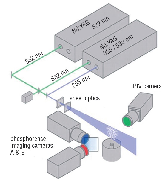
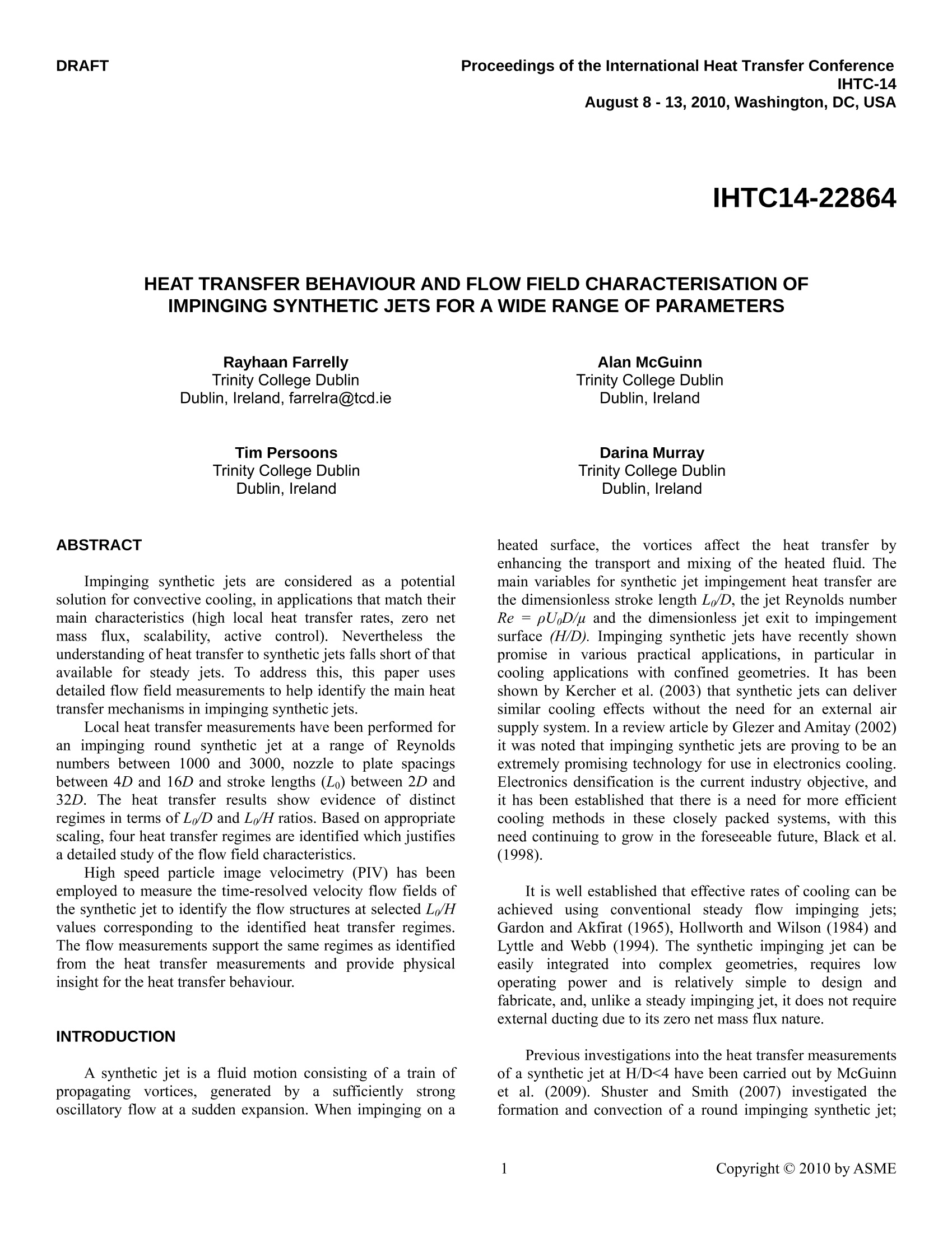
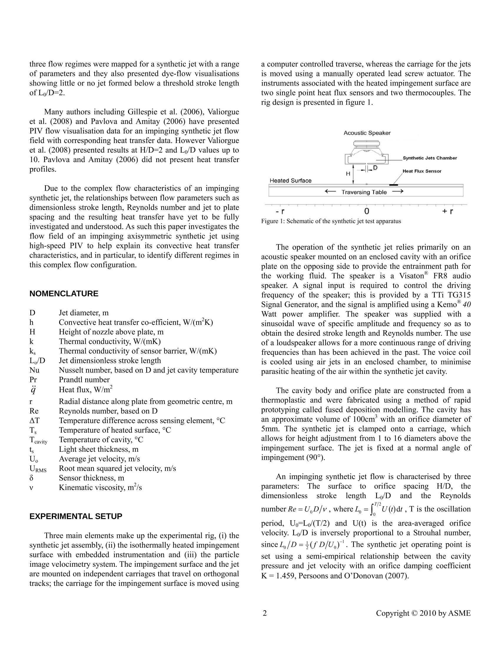
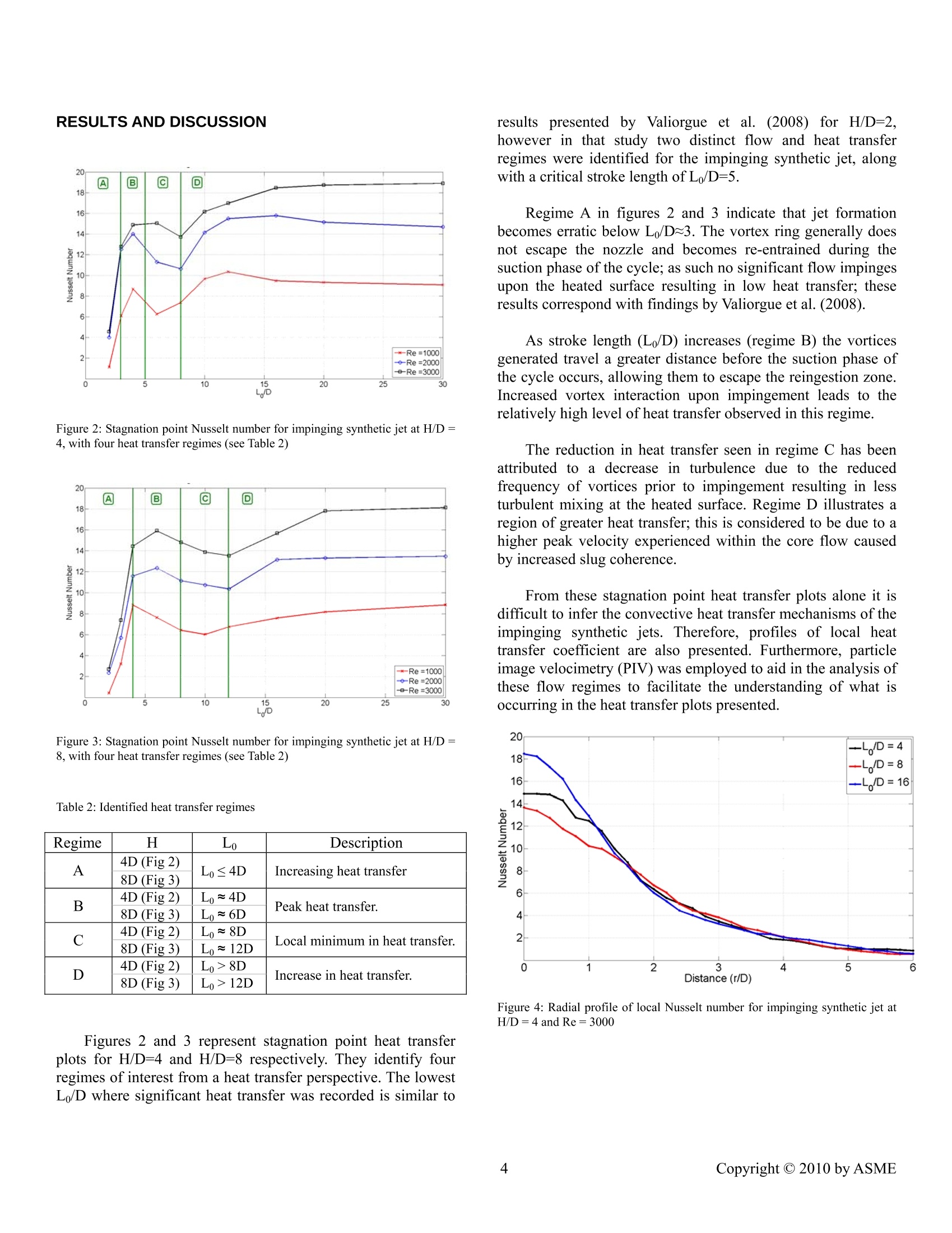
Proceedings of the International Heat Transfer ConferenceDRAFTIHTC-14August 8 -13, 2010, Washington, DC, USAIHTC14-22864 HEAT TRANSFER BEHAVIOUR AND FLOW FIELD CHARACTERISATION OFIMPINGING SYNTHETIC JETS FOR A WIDE RANGE OF PARAMETERS Rayhaan Farrelly Trinity College Dublin Dublin, Ireland, farrelra@tcd.ie Alan McGuinnTrinity College DublinDublin, Ireland ABSTRACT Impinging synthetic jets are considered as a potentialsolution for convective cooling, in applications that match theirmain characteristics (high local heat transfer rates, zero netmassflux, scalability, active control). Neverthelesstheunderstanding of heat transfer to synthetic jets falls short of thatavailable for steady jets. To address this, this paper usesdetailed flow field measurements to help identify the main heattransfer mechanisms in impinging synthetic jets. Local heat transfer measurements have been performed foran impinging round synthetic jet at a range of Reynoldsnumbers between 1000 and 3000, nozzle to plate spacingsbetween 4D and 16D and stroke lengths (Lo) between 2D and32D. The heat transfer results show evidence of distinctregimes in terms of L /D and L /H ratios. Based on appropriatescaling, four heat transfer regimes are identified which justifiesa detailed study of the flow field characteristics. High speed particle image velocimetry (PIV) has beenemployed to measure the time-resolved velocity flow fields ofthe synthetic jet to identify the flow structures at selected L/Hvalues corresponding to the identified heat transfer regimes.The flow measurements support the same regimes as identifiedfrom the heat transfer measurements and provide physicalinsight for the heat transfer behaviour. INTRODUCTION A synthetic jet is a fluid motion consisting of a train ofpropagating vortices, generateddby aasufficiently strongoscillatory flow at a sudden expansion. When impinging on a Trinity College Dublin Dublin, Ireland heated surface, thee vortices affect the heatttransfer byenhancing the transport and mixing of the heated fluid. Themain variables for synthetic jet impingement heat transfer arethe dimensionless stroke length Lo/D, the jet Reynolds numberRe =pUD/u and the dimensionless jet exit to impingementsurface (H/D). Impinging synthetic jets have recently shownpromise in various practical applications, in particular incooling applications with confined geometries. It has beenshown by Kercher et al. (2003) that synthetic jets can deliversimilar cooling effects without the need for an external airsupply system. In a review article by Glezer and Amitay (2002)it was noted that impinging synthetic jets are proving to be anextremely promising technology for use in electronics cooling.Electronics densification is the current industry objective, andit has been established that there is a need for more efficientcooling methods in these closely packed systems, with thisneed continuing to grow in the foreseeable future, Black et al.s(1998). It is well established that effective rates of cooling can beachievedusing conventional steady flow impinging jets;Gardon and Akfirat (1965), Hollworth and Wilson (1984) andLyttle and Webb (1994). The synthetic impinging jet can beeasily integratedinto) complex geometries, requires llowoperating power and is relatively simple to design andfabricate, and, unlike a steady impinging jet, it does not requireexternal ducting due to its zero net mass flux nature. Previous investigations into the heat transfer measurementsof a synthetic jet at H/D<4 have been carried out by McGuinnet al. (2009). Shuster and Smith (2007) investigated theformation and convection of a round impinging synthetic jet; three flow regimes were mapped for a synthetic jet with a rangeof parameters and they also presented dye-flow visualisationsshowing little or no jet formed below a threshold stroke lengthofL/D=2. Many authors including Gillespie et al. (2006), Valiorgueet al. (2008) and Pavlova and Amitay (2006) have presentedPIV flow visualisation data for an impinging synthetic jet flowfield with corresponding heat transfer data. However Valiorgueet al. (2008) presented results at H/D=2 and L/D values up to10. Pavlova and Amitay (2006) did not present heat transferprofiles. Due to the complex flow characteristics of an impingingsynthetic jet, the relationships between flow parameters such asdimensionless stroke length, Reynolds number and jet to platespacing and the resulting heat transfer have yet to be fullyinvestigated and understood. As such this paper investigates theflow field of an impinging axisymmetric synthetic jet usinghigh-speed PIV to help explain its convective heat transfercharacteristics, and in particular, to identify different regimes inthis complex flow configuration. NOMENCLATURE DJet diameter, mh H Convective heat transfer co-efficient, W/(mK) Height of nozzle above plate, m Thermal conductivity,W/(mK) Thermal conductivity of sensor barrier,W/(mK) L,/D Jet dimensionless stroke length MHr Nusselt number, based on D and jet cavity temperaturePrandtl number Heat flux, W/m Radial distance along plate from geometric centre, m Reynolds number, based on D Temperature difference across sensing element, °C Temperature of heated surface, ℃ Tcavity Temperature of cavity,℃ Light sheet thickness, m tU Average jet velocity, m/s URMs Root mean squared jet velocity, m/s 8 Sensor thickness, m V Kinematic viscosity, m/s EXPERIMENTAL SETUP Three main elements make up the experimental rig, (i) thesynthetic jet assembly, (ii) the isothermally heated impingementsurface with embedded instrumentation and (iii) the particleimage velocimetry system. The impingement surface and the jetare mounted on independent carriages that travel on orthogonaltracks; the carriage for the impingement surface is moved using a computer controlled traverse, whereas the carriage for the jetsis moved using a manually operated lead screw actuator. Theinstruments associated with the heated impingement surface aretwo single point heat flux sensors and two thermocouples. Therig design is presented in figure 1. Figure 1: Schematic of the synthetic jet test apparatus The operation of the synthetic jet relies primarily on anacoustic speaker mounted on an enclosed cavity with an orificeplate on the opposing side to provide the entrainment path forthe working fluid. The speaker issaa Visaton FR8 audiospeaker. A signal input is required to control the drivingfrequency of the speaker; this is provided by a TTi TG315Signal Generator, and the signal is amplified using a Kemo40Watt power amplifier. The speaker was supplied with asinusoidal wave of specific amplitude and frequency so as toobtain the desired stroke length and Reynolds number. The useof a loudspeaker allows for a more continuous range of drivingfrequencies than has been achieved in the past. The voice coilis cooled using air jets in an enclosed chamber, to minimiseparasitic heating of the air within the synthetic jet cavity. The cavity body and orifice plate are constructed from athermoplastic and were fabricated using a method of rapidprototyping called fused deposition modelling. The cavity hasan approximate volume of 100cm’ with an orifice diameter of5mm. The synthetic jet is clamped onto a carriage, whichallows for height adjustment from 1 to 16 diameters above theimpingement surface. The jet is fixed at a normal angle ofimpingement (90°). An impinging synthetic jet flow is characterised by threeparameters:DThee ssurface to corificeeSspacingH/D,thedimensionless stroke length L/D and the Reynoldsnumber Re=UD/v, where L=U(t)dt, T is the oscillationperiod,Uo=Lo/(T/2) and U(t) is the area-averaged orificevelocity. L/D is inversely proportional to a Strouhal number,since L /D=+(fD/U). The synthetic jet operating point isset using a semi-empirical relationship between the cavitypressure and jet velocity with an orifice damping coefficientK=1.459, Persoons and O'Donovan (2007). Table 1: Synthetic Jet Test Parameters ReynoldsNumber 1000 2000 3000 L/D Frequency (Hz) Frequency (Hz) Frequency (Hz) 30 10 21 31 20 15 30 46 16 19 38 58 12 26 51 77 10 31 61 92 8 38 76 116 6 51 101 154 4 77 150 232 3 100 200 308 2 150 312 460 The jet impinges onto a surface that consists of a 5mmthick flat copper plate measuring 425mm x 550mm. To theunderside of the plate a silicon rubber heater mat is glued witha thin layer of adhesive. The mat is approximately 1.1mm thick.The underside of the plate and mat assembly is insulated fromthesurroundings..The entireassembly issuchthatitapproximates a uniform wall temperature boundary condition.The system is typically operated at a surface temperature of40°C. The sensor utilised in this study is an RdF Micro-Foilheat flux sensor. The heat flux sensor is mounted flush with thesurface of the plate; to achieve this it was necessary to embedthe sensor in the plate by machining a groove in the surface andgluing it down using a thermally conductive epoxy. The sensoris positioned centrally on the plate, and together with the jetandplate carriage arrangement,allow for 1heatttransfermeasurements beyond 20 diameters from the geometric centreof the jet. In this study, testing has only been concerned withinthe region of 1 to 6 diameters from the geometric centre of thejet. The Micro-Foilheat flux sensor measures the temperaturedifferential across a known thermal barrier using a differentialthermopile. The heat flux through the sensor is based on thefollowing equation: Where AT is1Sthe temperature difference acrossthethickness (8) of the barrier and k, is the thermal conductivity ofthe barrier (kapton). A single pole T-type thermocouple is alsoembedded in this sensor to measure the local temperature. The Micro-Foil heat flux sensor was calibrated using acontoured nozzle with a diameter of 13mm. For a roundunconfined steady impinging jet, Liu and Sullivan (1996) have shown that at low H/D (< 2) the convective heat transfercoefficient at the stagnation point is independent of nozzleheight and is predicted well by the following correlation for Rebetween 10000 and 30000 The voltage produced by the Micro-Foil heat flux sensorwas recorded when the sensor was placed at the stagnationpoint under the impinging jet. The height of the nozzle abovethe heated impingement surface was 0.75D. The Reynoldsnumber was varied from 10000 to 30000. The calculated heatflux was plotted against the voltage produced under the testconditions, which produced an R² value of 0.9975. The heattransfer co-efficient is calculated using the following equation: and1the correspondingN uNsus:elt number (equation4)isdetermined with the jet temperature as a reference. The heat transfer rig used in this paper is similar to that used byO'Donovan and Murray (2007). Flow measurements have been performed using ParticleImage Velocimetry (PIV). The PIV system comprises of aQuantronix Darwin-Duo Nd:YLF twin cavity laser (up to 15mJ at 1000 Hz, 527 nm) and a LaVision HighSpeedStar6CMOS camera (1024x1024 pixels, 12 bit) with a Sigma 50-105mm lens. A glycol-water aerosol is used for seeding, withparticle diameters between 0.2 and 0.3um. Several steps were taken to minimise reflection whenperforming PIV measurements on the synthetic jet. To avoidreflection on the orifice plate and the impingement surface, (a)the light sheet thickness is reduced to approximately, t=1mmacross the viewing window, (b) the orifice plate was paintedfluorescent orange, (C) the impingement surface was paintedmatt black, and (d) a narrow band pass filter that allows onlygreen light into the camera lens was utilised. The camera wastilted slightly to approximately +2° to further reduce reflectionsfrom the impingement surface. Perspective distortion wascalibrated using LaVision’s Davis software. The velocity fields recorded have been processed withLaVision’sDavis7.2.2 software using multi-grid cross-correlation with an interrogation window size decreasing from64x64 to 32x32 pixels at 50% overlap, with further processingof the PIV flow visualisation plots in MATLAB. Figure 2: Stagnation point Nusselt number for impinging synthetic jet at H/D=4, with four heat transfer regimes (see Table 2) Figure 3: Stagnation point Nusselt number for impinging synthetic jet at H/D=8, with four heat transfer regimes (see Table 2) Table 2: Identified heat transfer regimes Regime H L0 Description A 4D (Fig 2) Lo≤4D Increasing heat transfer 8D (Fig 3) B 4D (Fig2) L0~4D Peak heat transfer. 8D (Fig 3) L0~6D C 4D (Fig 2) L0~8D Local minimum in heat transfer. 8D (Fig 3) Lo~12D D 4D (Fig 2) L0>8D Increase in heat transfer. 8D (Fig 3) Lo>12D Figures 2 and 3 represent stagnation point heat transferplots for H/D=4 and H/D=8 respectively. They identify fourregimes of interest from a heat transfer perspective. The lowestL/D where significant heat transfer was recorded is similar to resuI oresented by Valiorgue et al. (2008) for FH//DD=2however in that study two distinct flow and heat transferregimes were identified for the impinging synthetic jet, alongwith a critical stroke length of L/D=5. Regime A in figures 2 and 3 indicate that jet formationbecomes erratic below L/D~3. The vortex ring generally doesnot escape the nozzle and becomes re-entrained during thesuction phase of the cycle; as such no significant flow impingesupon the heated surface resulting in low heat transfer; theseresults correspond with findings by Valiorgue et al. (2008). As stroke length (L/D) increases (regime B) the vorticesgenerated travel a greater distance before the suction phase ofthe cycle occurs, allowing them to escape the reingestion zone.Increased vortex interaction upon impingement leads to therelatively high level of heat transfer observed in this regime. The reduction in heat transfer seen in regime C has beenattributed to a decrease in turbulence due to the reducedfrequency of vortices prior to impingement resulting in lessturbulent mixing at the heated surface. Regime D illustrates aregion of greater heat transfer; this is considered to be due to ahigher peak velocity experienced within the core flow causedby increased slug coherence. From these stagnation point heat transfer plots alone it isdifficult to infer the convective heat transfer mechanisms of theimpinging synthetic jets. Therefore, profiles of local heattransfer coefficient are also presented. Furthermore, particleimage velocimetry (PIV) was employed to aid in the analysis ofthese flow regimes to facilitate the understanding of what isoccurring in the heat transfer plots presented. -L/D=4-D=8 -/D=16 Figure 4: Radial profile of local Nusselt number for impinging synthetic jet atH/D=4 and Re=3000 Figure 5: Radial profile of local Nusselt number for impinging synthetic jet atH/D=8and Re=3000 Figures 4 and 5 illustrate the radial heat transfer profiles ofa synthetic jet for three different Lo/D values of 4, 8, 16, andfor a jet Reynolds number of 3000. Values presented show anoverall maximum at the stagnation point, with local heattransfer decreasing with increasing radial distance. This trendwas observed in all cases. Figure 4 corresponds with the stagnation point heattransfer plot presented in figure 2 for a jet Reynolds number of3000. Each radial profile coincides with a specific regime, i.e.the radial profile L/D=4 lies within regime B. It is evidentfrom these profiles that increasing the L/D can effect greaterheat transfer. Likewise the vortex interaction caused by smallerstroke lengths results in a lower yet broader radial Nusseltnumber profile. 8 Figure6: Timeieaveragedvvielocityandturbulence intensity distribution of impingingsynthetic jett((H/D=8,L/D=4, Re=3000,Regime B) Figure 7: Time averaged velocity and turbulenceintensity distribution of impinging synthetic jet(H/D=8,L/D=8, Re=3000, Regime C) Figure Time averaged velocityandturbulence intensity distribution of impingingsynthetic jet (H/D=8, Lo/D=16, Re=3000,Regime D) For the sake of clarity in the phase locked Particle ImageVelocimetry plots presented only 1 of every 2 vectors in thevertical direction has been plotted. The overall result makes theplot easier to interpret. Figures 6 through 8 represent the time averaged flow fieldand turbulence intensity of the synthetic jet at H/D=8, Re=3000and three different stroke lengths (L/D) 4, 8 and 16. Thecolour bar on the right hand side of figure 8 corresponds toturbulence intensity, URMS/U. In figure 6 for L /D=4, there is a lower turbulence intensityexperienced within the jet core. At this low stroke length thereare a greater number of vortices generated because of thehigher driving frequency. As can be seen in figure 11, thevortices convect away from the nozzle, increased interactionresults in vortex breakdown and an overall reduction inturbulence intensity. Increasing the stroke length (L /D) to 8 infigure 7, it can be seen that that the turbulence intensityincreases. This increase is particularly evident within the coreflow of the jet. The reduced mixing is a direct result of thelarger stroke length and the reduceddriving frequencyproducing less vortical interactions upon impingement. Thiscan be seen in figure 12. Figure 8 displays the greatestturbulence intensity for this H/D and jet Reynolds number. Arelatively large stroke length (Lo/D=16) and low actuatingfrequency result in a slug like core flow impinging upon theplate, this can be seen in figure 13. This regime experiences noevident vortex interaction prior to impingement. The largeturbulence intensity experienced at this stroke length is a resultof the periodic nature of the highly coherent core. In contrast tothe L/D=4 in figure 6, the large turbulence intensity extends allthe way to the impingement surface. -0.6 -0.4 -0.2 0 0.2 0.4 0.6 Figure 9: Phase-locked flow field and dimensionless vorticity ωD/Udistribution of impinging synthetic jet at the end of the ejection phase (H/D=4,Lo/D=2,Re=3000,p=270°) Figure 9 shows the PIV flow field and dimensionlessvorticity for H/D=4,L/D=2, Re =3000. The colour bar infigure 9 represents normalised vorticity ωD/Uo, where bluesignifies clockwise movement, and red anti-clockwise. Thisplot helps to illustrate the fact that the synthetic jet is just aboutforming, i.e. the vortex has not been able to propagate awayfrom the orifice, and the formation vortex ring shown in figure9 after full ejection of the synthetic jet is unable to escape thenear vicinity of the orifice and is reingested into the orificeduring the suction phase of the synthetic jet cycle. Shuster andSmith (2007) reported that no vortices were phase locked to the actuating driver frequency at 1≤L /D≤3; the results presented infigure 9 are in agreement with this finding. This effect isknown to occur at non-dimensional stroke lengths of L/D<2,which is close to the limiting condition for vortex formationand advection. For values of L/D≥2 it was found that thesynthetic jet achieved higher heat transfer than the syntheticjets formed at L /D<2 for the same jet Reynolds numbers. The flow field presented in figure 10 corresponds with theNusselt number profile in figure 4 for L/D=16. Greatest heattransfer is experienced at these parameters. The flow structureseen in figure 10 highlights the almost discrete nature of eachperiod of the jet at this L/D; it is observed that no significantinteractions between ejections occur. During each ejection phase of the cycle the flow impacts asa single slug with a much greater length scale than that of theheight above the surface (H/D). This type of coherent coreimpingement results in a significantly higher velocity uponimpact and the corresponding elevation in11heatt transferobserved (figure 4). Figure 10: Phase-locked flow field and dimensionless vorticity oD/Udistribution of impinging synthetic jet at the end of the ejection phase (H/D=4,L/D=16,Re=3000,=270°) 8 Figure 11: Phase-locked flow field and dimensionless vorticity oD/Udistribution of impinging synthetic jet at the end of the ejection phase (H/D=8,L/D=4,Re=2000,=270°) 4 Figure 12: Phase-locked flow field and dimensionless vorticity oD/Udistribution of impinging synthetic jet at the end of the ejection phase (H/D=8,L/D=8, Re=2000,=270°) Figure 13: Phase-locked flow field and dimensionless vorticity ωD/Udistribution of impinging synthetic jet at the end of the ejection phase (H/D=8,L/D=16,Re=3000,p=270°) CONCLUSIONS Stagnation point heat transfer data and Nusselt numberdistributions have been presented for an impinging syntheticjet. Flow field data has also been presented in the form of timeaveraged velocity and turbulence intensity distribution, andphase-locked 1flow field1and dimensionlessvorticitydistributions for H/D values of 4 and 8, and Reynolds numbers1000 to 3000 and L/D of 2 to 16. Four different stagnation point heat transfer regimes wereidentified and investigated using corresponding radial heattransfer profiles and flow field data. Results obtained showed a strong correlation between theheat transfer data and the flow field data; specifically that of theinteractions of the vortices at low L/D values and the effectiveheat transfer. It was also noted that a slug flow regime wasidentified at large stroke lengths which also provided increasedheat removal rates. Similar trends to those identified in this paper have beenobserved by authors such as Valiorgue et al. (2008) and Shusterand Smith (2007). ACKNOWLEDGMENTS The authors acknowledge the technical support staff of theMechanical and Manufacturing Engineering Department ofTrinity College Dublin. The project is part funded by Science Foundation Ireland(SFI))grant number 07/RFP/ENMF220, the Centre forTelecommunications Value-Chain Research (CTVR), and IrishResearch Council for Science, Engineering and Technology(IRCSET). REFERENCES Black W.Z., Glezer A., Hartley J.G., (1998)“Heat TransferModules for Cooling Electronics Packages” IInternationalSymposium on Advanced Packaging Materials ( Gardon R ., A kfirat J.C., (1965) “ The role o f turbulence i n determining t h e heat-transfer c h aracteristics of impinging jets”Internationa l Journa l of Heat and Mass T r ansfer, V olume 8 , Issue 10, October 1965, Pages 1261-1272 ) Gillespie M., Black W., Rinehart, C., Glezer, A., (2006)“LocalConvective Heat Transfer from a Constant Heat Flux Flat PlateCooled by Synthetic Air Jets”ASME Journal of Heat Transfer,Vol. 128. ( Glezer A., Amitay M., (2002)“Synthetic J ets”Annual Review Fluid Mechanics, 34:503-29. ) ( Holman R. , Ut t urkar Y., Mi t tal R. , Sm i th B. L ., Cattafesta L., (2005)“ F ormation Cr i terion for S y nthetic J e ts” AIAA JournalVol. 43, No. 1 0. ) ( Hollworth B .R., W ilson S.I., (1984) “ Entrainment e f fects o n impingement h e at t r ansfer I : Measurements o f he a ted jet velocity and temperature distributions and recovery temperatures on target surface” Journal of Heat T ransfer, vol. 106,n°4, pp.797-803 ) ( Kercher D. S., L ee J. B., B rand O . , A l len M . G. , Glezer A. , (2003) “ Microjet c ooling devices for thermal management o felectronics”J. Chem. Theory Comput.,26 _ 2 _ , p p.359-366. ) ( Lyttle D., Webb B., 1 994.“A i r jet impingement heat transfer at low n ozzle-plate s pacings”Int. J. H eat Mass Tr a nsfer 37, pp. 1687-1697. ) McGuinn A., Persoons T., O’Donovan T. S., Murray D. B.,(2009) “Heat transfer and air temperature measurements of animpinging synthetic air jet" Turbulence, Heat and MassTransfer 6, Begell House Inc. New York. O'Donovan T. S., Murray, D. B.,(2007) "Jet impingement heattransfer - Part I: Mean and root-mean-square heat transfer andvelocity distributions," International Journal of Heat and MassTransfer, vol. 50, pp.3291-3301. Pavlova, A. and Amitay, M., (2006)“Electronic Cooling UsingSynthetic Jet Impingement”ASME Journal of Heat Transfer,128 pp897-907. Persoons T1., O'Donovan T. S., (2007)“A pressure-basedestimateof syntheticjjet velocity” Physics(of IFluids19(12):128104. Smith B. L., Glezer A., (1998)“The formation and evolution ofsynthetic jets"Physics of Fluids 10:2281-2297. Shuster J. M., Smith D. R., (2007)“Experimental study of theformation and scaling of a round synthetic jet" Physics ofFluids, 19:045109 Valiorgue P., Persoons T., McGuinn A., Murray D. B., (2008)"Heat transfer mechanisms in an impinging synthetic jet for asmall jet-to-surface spacing," Experimental Thermal and FluidScience,vol. 33, pp. 597-603 Copyright by ASME
确定


还剩6页未读,是否继续阅读?

产品配置单


北京欧兰科技发展有限公司为您提供《冲击合成射流中热量传导行为,流场特征,速度场,速度矢量场检测方案(粒子图像测速)》,该方案主要用于其他中热量传导行为,流场特征,速度场,速度矢量场检测,参考标准--,《冲击合成射流中热量传导行为,流场特征,速度场,速度矢量场检测方案(粒子图像测速)》用到的仪器有LaVision 热成像粒子成像测速系统(PIV)、Imager LX PIV相机
相关方案
更多
该厂商其他方案
更多