


方案详情
文
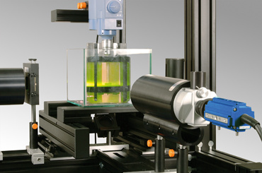
采用LaVision的在液体中的激光诱导荧光测量系统FluidMaster进行了降膜在倾斜加热箔上的时间分辨浓度和温度分布测量,获得了时空分辨传热数据。
方案详情

SISpatiote y resolved heat transfer measurements in falling-n falling-film flows over an inclined heated f Imperial CollegeLondon SPATIOTEMPORALLY RESOLVED HEAT TRANSFER MEASUREMENTS INFALLING-FILM FLOWS OVER AN INCLINED HEATED FOIL Alexandros Charogiannis, Baptiste Heiles,Richard Mathie, Omar K. Matar, and Christos N. MarkidesClean Energy Processes (CEP) Laboratory, Department of Chemical Engineering, Imperial College London Measurements of unsteady and conjugate heat transfer were carried out in harmonically forced,gravity-driven liquid films flowing over a resistively heated inclined titanium foil, by simultaneousapplication of planar laser-induced fluorescence (PLIF) imaging and infrared (IR) thermography (Mathie& Markides, 2013; Mathie, Nakamura & Markides, 2013; Markides, Mathie & Charogiannis, 2016). Quantitative, spatiotemporally resolved and simultaneously conducted measurements are reported forthe local and instantaneous film-height, film free-surface temperature, liquid-solid interfacetemperature, wall heat-flux, and finally the local and instantaneous heat transfer coefficient (HTC).This research effort was motivated by the strong demand for spatiotemporally resolved heat-transferdata in planar falling films, which can be harnessed to further our understanding of the underlying heat-transfer mechanisms, facilitate the development and validation of advanced modelling tools and,ultimately, improve the performance and reduce the cost of equipment. EXPERIMENTAL ARRANGEMENT The experimental arrangement comprises a preparationsection where the film flows are initiated, and a closedflow-loop via which the liquid (20% ethanol,80% waterb.v.) circulates to the test section. The main test-section(Fig. 1) comprises an electrically heated Titanium foilinclined at 40°.A 2-D PLIF imaging technique was usedto characterize the local and instantaneous film-thicknessand film free-surface temperature simultaneously, byseeding the liquid with Rhodamine-B dye. The dye wasexcited using a Nd:YAG laser (532 nm, 100 Hz), andfluorescence images were collected using a pair ofLaVision HS 500 CMOS cameras. The foil (un-wetted)underside temperature was measured simultaneously bya mid-wave IR (Cedip Titanium) camera. FIGURE 1: Test section schematic. IMAGE PROCESSING xmmFIGURE 2: Typical perspective distortioncorrected PLIF image. Raw PLIF images were corrected for perspectivedistortion (Fig. 2) by employing a calibration graticule-target and a pinhole projection model. Differentmethods were devised to systematically identify the filmfree-surface; of these, a gradient method was found toproduce the most accurate film-thickness estimates andsmoothest thickness profiles. The fluorescence intensitynear the free-surface was used to measure theinterface temperature, following a series of calibrationexperiments that employed thin thermocouples. Thestandard deviation between the thermocouple and PLIFmeasurements was ±0.5 C, a value used as anestimate of the error associated with the PLIFtemperature measurement. Additional errors, however,ensue due to light distortion effects when the interfaceis strongly curved (hydrodynamic waves); in this case,the maximum error associated with the PLIF-basedtemperature measurement increases to~1.3°℃. FIGURE 3: Typical perspective distortioncorrected IR image of the film-freetemperature. Perspective distortion corrections were also applied tothe raw IR images by employing an affine transformationmethod, while a 1-D thermal conduction model withconstant heat generation by resistive heating was usedto describe the thermal response of the foil totemperature fluctuations imposed on one of its sides, inthis case the top side in contact with the ligyid with theother (bottom) side assumed to be adiabatic. The spatialalignment accuracy between the simultaneous PLIF andIR images was better than 2 mm. PHENOMENOLOGICAL OBSERVATIONS LIF T[C 25 -20 -10 10 20 z[mm] FIGURE 4: Spanwise profile of the film free-surface FIGURE 5: Spanwise spatial profile of the film thickness temperature obtained simultaneously by PLIF and IR obtained by PLIF, simultaneously with the temperature profile imaging shown in Fig. 4 Figure 3 reveals regularly spaced, finger-like structures developing in the flow direction, while Fig. 4presents quantitativRHie free-surface temperature profiles recovered simultaneously by IR thermographyand PLIF, at the measurement location indicated in Fig. 3 (285 mm downstream of the flow inlet).Figure 5 shows the film height obtained from the same PLIFimage. The liquid film is thicker where the surface temperature is lower and vice versa, with the two troughs inthe film thickness measurement corresponding to the two larger peaks in the surface temperaturemeasurement. From direct observations of many such image sequences, it appears that the advent ofrivulet structures, such as the one discussed above, manifests itself in the development of Marangoniflows at the film surface, driven by temperature-induced surface tension gradients. ACKNOWLEDGEMENTS QUANTITATIVE HEAT TRANSFER CHARACTERIZATION The spatiotemporal evolution of the film thickness and free-surface temperature measuredsimultaneously by PLIF at a distance ofx=185 mm downstream of the inlet over a 1.8 s time interval isplotted in Fig. 6, alongside the substrate-foil temperature measured by the IR camera. In this figure theflow has Re = 251 and an imposed heat-flux set to q=3.6 W cm2. High free-surface temperatures areobserved in thin film-trough regions and vice versa. The local film-thinning shows a high degree ofcorrelation with the lower temperature regions on the foil underside which are, however, observed with aslight delay compared to the corresponding trough and high temperature regions. This delay, appears tobe =0.1 s, and is most probably attributed to the thermal inertia of the foil. Finally, locally higher HTCsensue in thin-film regions (troughs), as more heat is extracted from the substrate. Figure 7 shows the evolutions of the local and instantaneous heat flux q, HTC and Nu number. Asexpected, the Nu and HTC are highest where the film is thinnest. The variation in the heat flux amountsto approximately4% of the imposed mean heat-flux and the mean Nu amounts to about 2.8. The HTCvariations are in the range 1-3 kW K-1m-2. 4cz [mm] z[mm] z[mm] FIGURE 6: Comparison between the film height (plot on the left) and the free-surface temperature (middle plot) measured byPLIF,and the foil underside temperature measured by IR thermography (plot on the right)). mm z[mm FIGURE 7: Local and instantaneous heat flux q, HTCh, and Nusselt number Nu for a flow with Re=179,q =3.6 W cm-2. New insight into the effects of unsteadiness onthe observed HTC enhancement can beobtained by examining joint-PDFs generatedfrom separate sets of data corresponding todifferent Re (Fig. 8). For the lowest Re flows(Re= 68), the majority of the experimentaldata appear close to the theoretical Nusseltprediction, but the film thickness does notshow considerable variations. For the flow atRe = 720, the trend described by the Nusseltsolution is reproduced, with the HTC valuesbeing, however, globally higher than theNusseltprediction. Moreover, theHTCdependence on the film thickness becomesweaker than that in the Nusselt solution for FIGURE 8: PDFs of the HTC, plotted against film thickness,for data acquired under: Re= 68; Re=720 and Re =1300. thicker films. Further increasing the Re from 720 to 1300 boosts the observed HTC values even further,and accentuates the previously noted observations, with the HTC appearing almost decoupled from thefilm thickness especially for thicker films (>1 mm). This decoupling at higher film thicknesses and high Remay be linked to flow recirculation; as the Re increases, the flow velocity surpasses the wave velocity,resulting in flow recirculation underneath the wave crest. CONCLUSIONS A combined PLIF-IR thermography technique was developed and employed for the detailed experimentalcharacterization of unsteady and conjugate heat-transfer in planar, gravity-driven liquid films flowing overan inclined heated metal foil. The results presented herein quantify the HTC enhancement at lower film-thickness values and also capture the overall HTC variations due to the fluctuating film-thickness; theyalso suggest that the magnitude of the true HTC can be significantly higher than HTC predictions basedon Nusselt theory, by up to a factor 3 in some cases. A number of unsteady flow phenomena linked to theinterface waviness are believed to contribute towards this enhancement. REFERENCES Mathie, R. and Markides, C.N., Heat transfer augmentation in unsteady conjugate thermal systems -Part I: Semi-analytical 1-D framework, Int. J. Heat Mass Transf. 56 (2013)802-818.Mathie, R., Nakamura, H. and Markides, C.N., Heat transfer augmentation in unsteady conjugatethermal systems-Part ll: Applications, Int. J. Heat Mass Transf. 56 (2013)819-833.Markides, C.N., Mathie, R. and Charogiannis,A., An experimental study of spatiotemporally resolved heat transfer in thin liquid-film flows falling over an inclined heated foil, Int. J. Heat Mass Transf. 93(2016)872-888. Measurements of unsteady and conjugate heat transfer were carried out in harmonically forced, gravity-driven liquid films flowing over a resistively heated inclined titanium foil, by simultaneous application of planar laser-induced fluorescence (PLIF) imaging and infrared (IR) thermography (Mathie & Markides, 2013; Mathie, Nakamura & Markides, 2013; Markides, Mathie & Charogiannis, 2016).Quantitative, spatiotemporally resolved and simultaneously conducted measurements are reported for the local and instantaneous film-height, film free-surface temperature, liquid-solid interface temperature, wall heat-flux, and finally the local and instantaneous heat transfer coefficient (HTC).This research effort was motivated by the strong demand for spatiotemporally resolved heat-transfer data in planar falling films, which can be harnessed to further our understanding of the underlying heat-transfer mechanisms, facilitate the development and validation of advanced modelling tools and, ultimately, improve the performance and reduce the cost of equipment.
确定


还剩1页未读,是否继续阅读?

产品配置单

北京欧兰科技发展有限公司为您提供《在倾斜加热箔上的降膜中浓度场和温度场检测方案(在线反应分析)》,该方案主要用于其他中浓度场和温度场检测,参考标准--,《在倾斜加热箔上的降膜中浓度场和温度场检测方案(在线反应分析)》用到的仪器有液体混合过程分析测试系统、LaVision DaVis 智能成像软件平台
相关方案
更多
该厂商其他方案
更多