


方案详情
文
Recent kinematic and hydrodynamic studies on fish
median fins have shown that dorsal fins actively produce
jets with large lateral forces. Because of the location of
dorsal fins above the fish’s rolling axis, these lateral forces,
if unchecked, would cause fish to roll. In this paper we
examine the hydrodynamics of trout anal fin function and
hypothesize that anal fins, located below the fish’s rolling
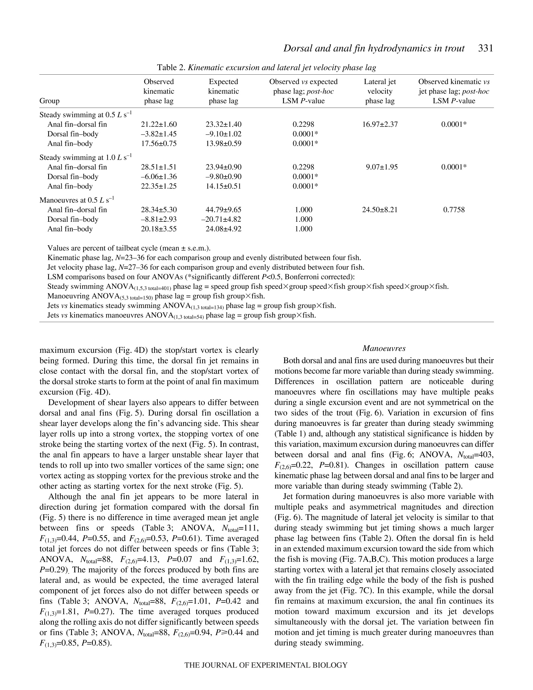
axis, produce similar jets to the dorsal fin and help balance
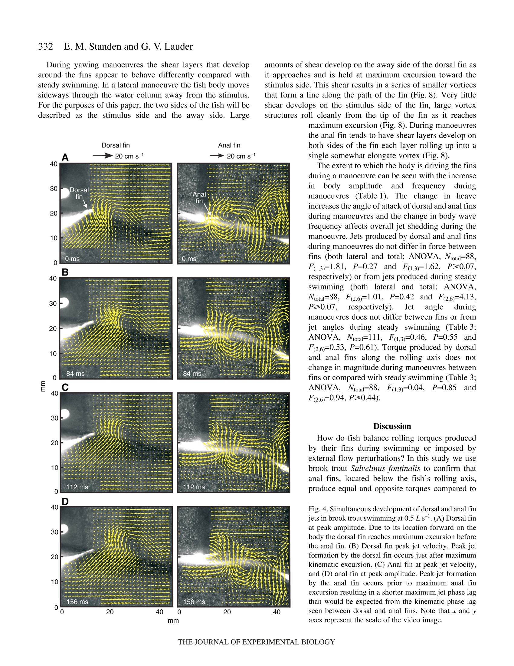
rolling torques during swimming. We simultaneously
quantify the wake generated by dorsal and anal fins in
brook trout by swimming fish in two horizontal light
sheets filmed by two synchronized high speed cameras
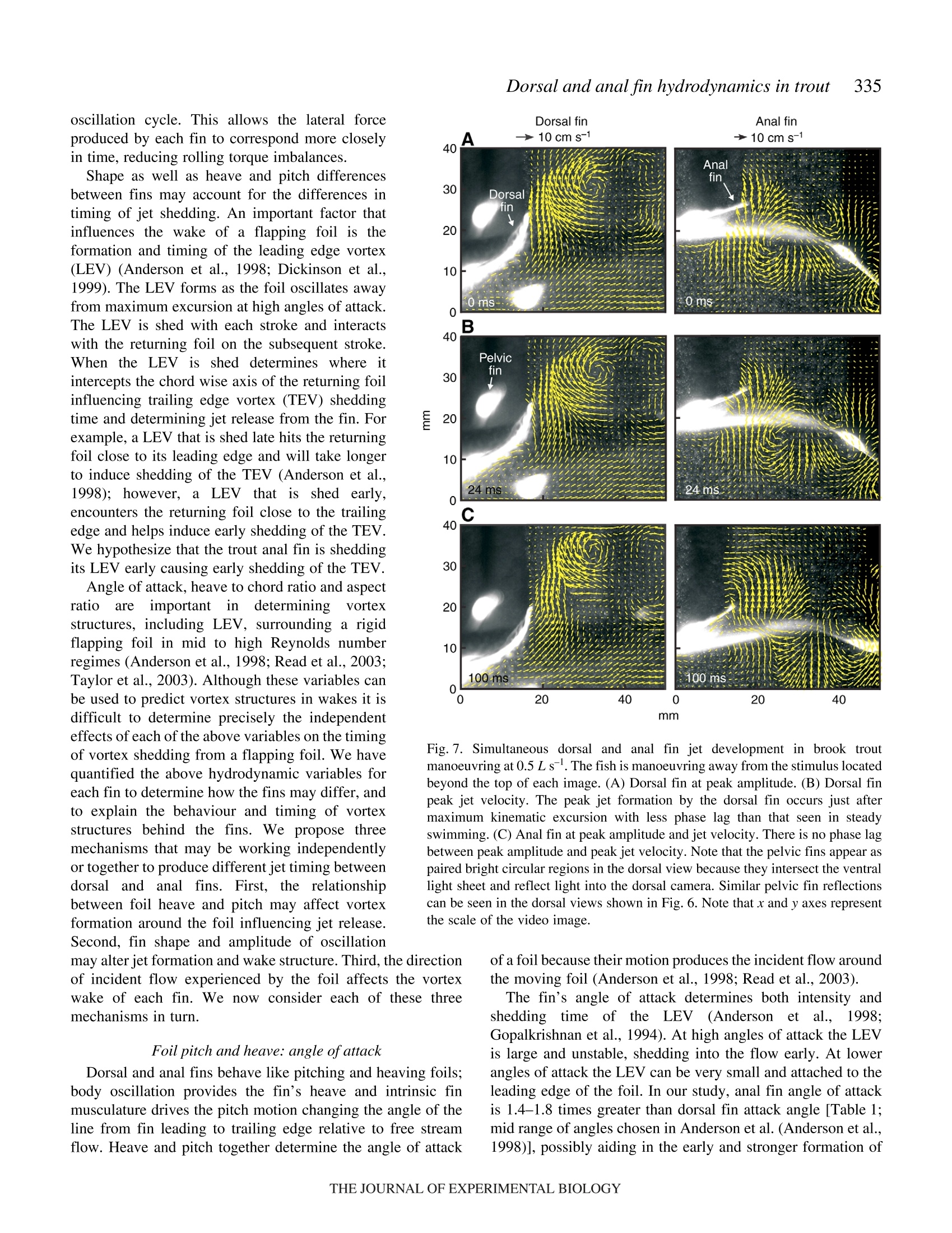
during steady swimming and manoeuvring. Six major
conclusions emerge from these experiments.
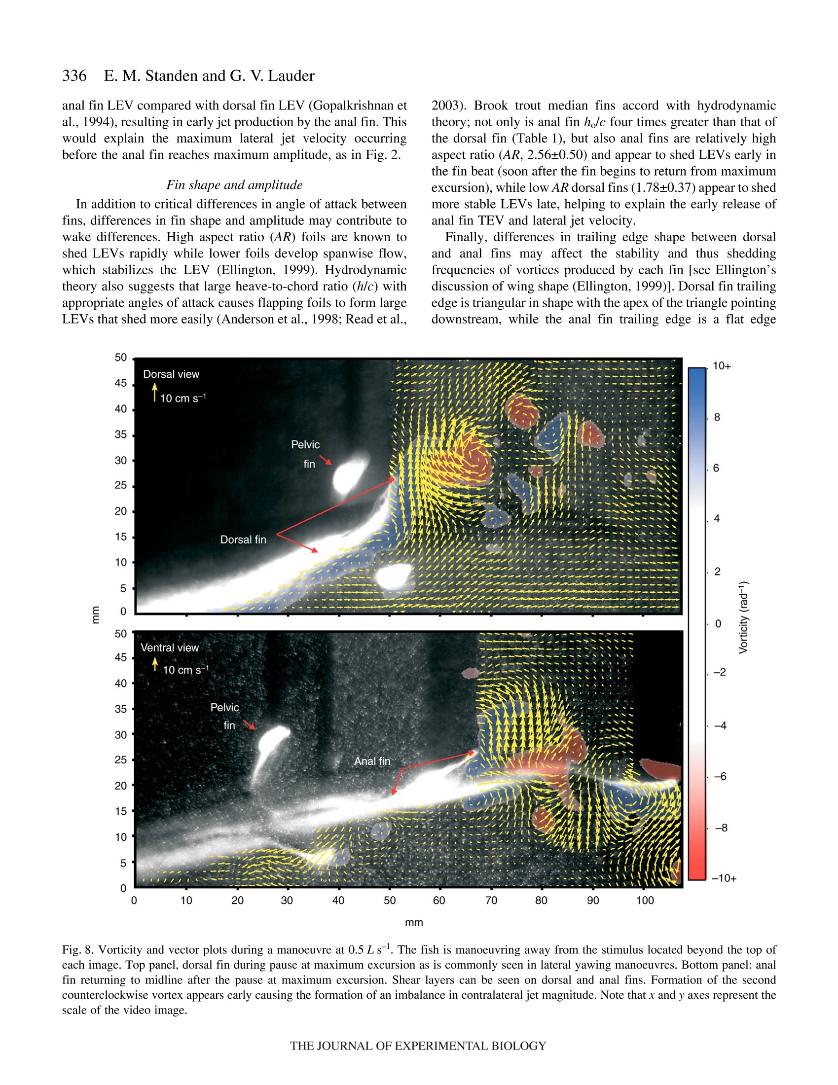
方案详情

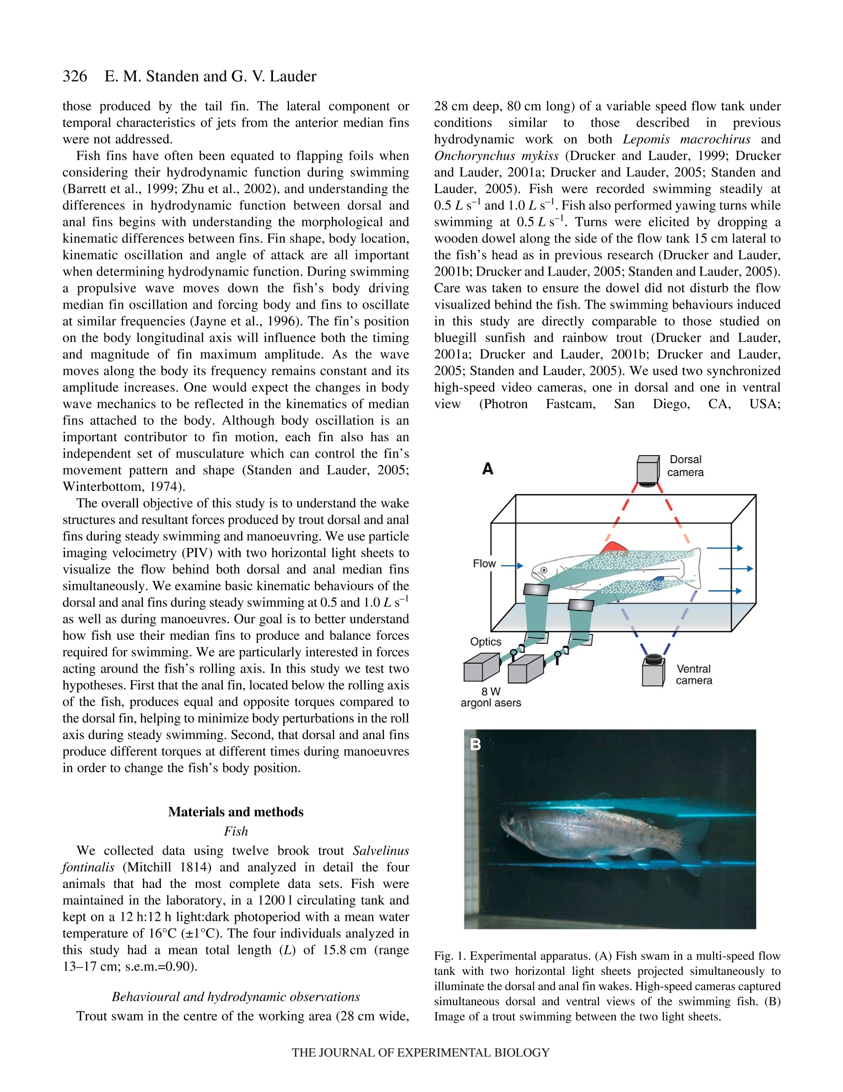
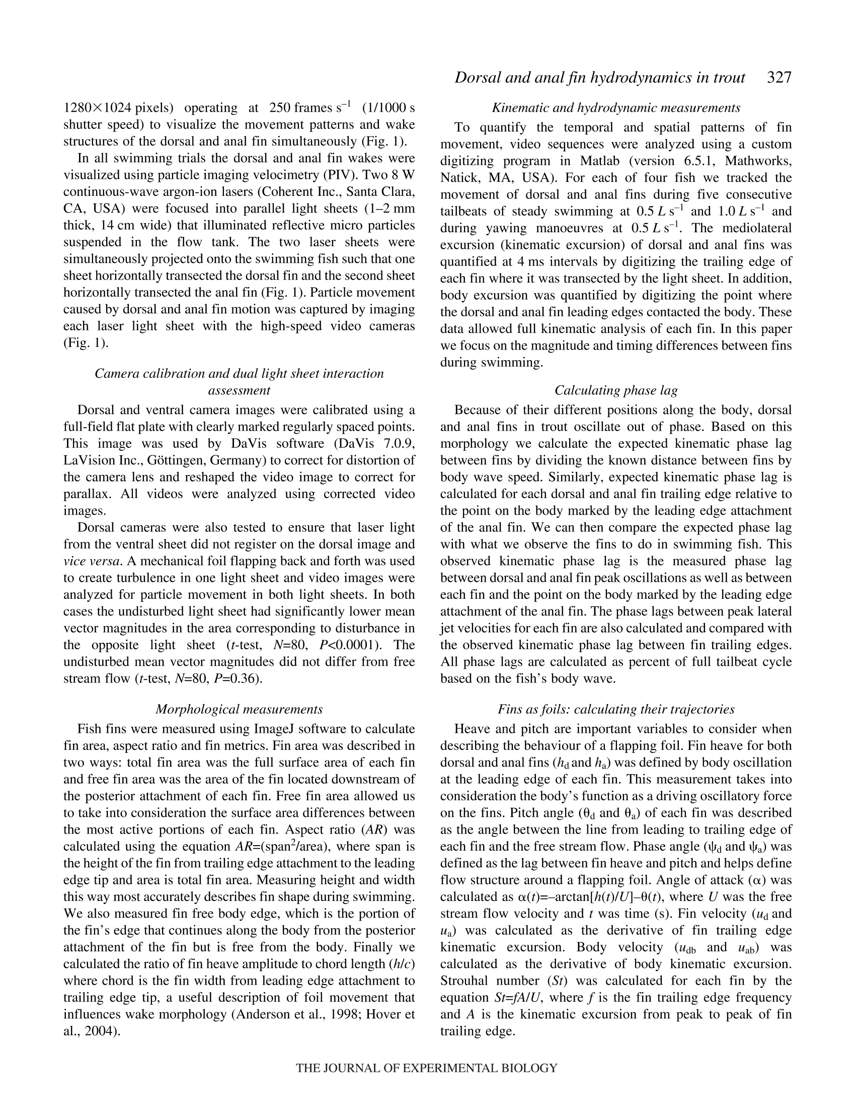
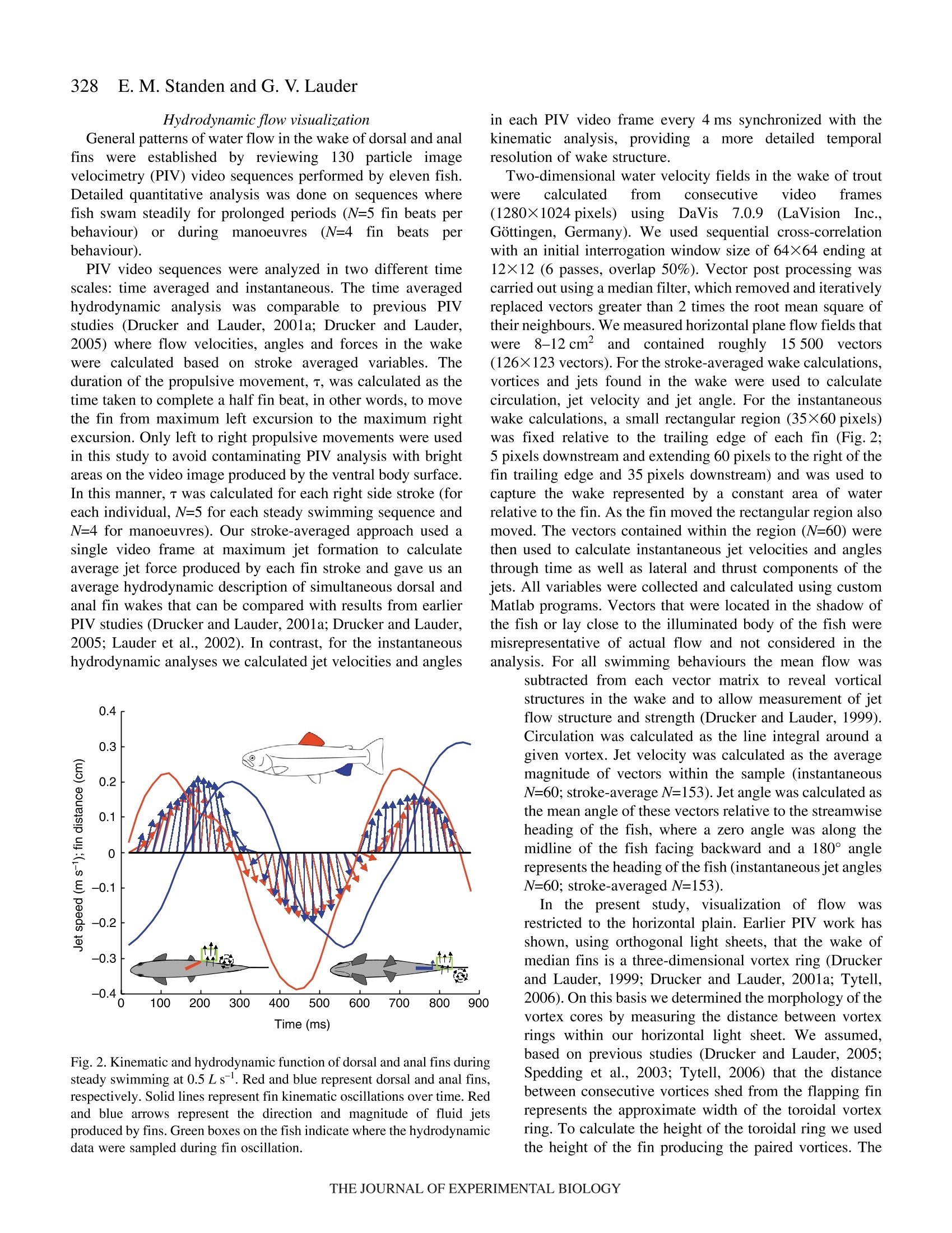
325The Journal of Experimental Biology 210, 325-339Published by The Company of Biologists 2007doi:10.1242/jeb.02661 326E. M. Standen and G. V.Lauder Hydrodynamic function of dorsal and anal fins in brook trout (Salvelinusfontinalis) E.M. Standen* and G. V. Lauder Museum of Comparative Zoology, Harvard University, 26 Oxford Street, Cambridge, MA 02138, USA *Author for correspondence (e-mail: standen@fas.harvard.edu) Accepted 21 November 2006 Recent kinematic and hydrodynamic studies on fishmedian fins have shown that dorsal fins actively producejets with large lateral forces. Because of the location ofdorsal fins above the fish’s rolling axis, these lateral forces,if unchecked, would cause fish to roll. In this paper weexamine the hydrodynamics of trout anal fin function andhypothesize that anal fins, located below the fish’s rollingaxis, produce similar jets to the dorsal fin and help balancerolling torques during swimming. We simultaneouslyquantify the wake generated by dorsal and anal fins inbrook trout by swimming fish in two horizontal lightsheets filmed by two synchronized high speed camerasduring steady swimming and manoeuvring. Six majorconclusions emerge from these experiments. First, anal fins produce lateral jets to the same side asdorsal fins, confirming the hypothesis that anal finsproduce fluid jets that balance those produced by dorsalfins. Second, in contrast to previous work on sunfish,neither dorsal nor anal fins produce significant thrustduring steady swimming; flow leaves the dorsal and analfins in the form of a shear layer that rolls up into vorticessimilar to those seen in steady swimming of eels. Third,dorsal and anal fin lateral jets are more coincident in timethan would be predicted from simple kinematic Introduction A biomechanical trade off exists between stability andmanoeuvrability in many animals, and fish are known to beparticularly unstable in the roll axis (Webb, 2006). Comparedto pitching and yawing instabilities, controlling for roll appearsto be important as fish respond most consistently and quicklyto perturbations that cause rolling (Webb, 2004). How fishcontrol for rolling perturbations is unknown. Previous experimental hydrodynamic studies have shown alarge lateral component to the jets produced by the dorsal finin bluegill sunfish Lepomis macrochirus and rainbow troutOnchorynchus mykiss (Drucker and Lauder, 2001a; Druckerand Lauder, 2005). The location of the dorsal fin above therolling axis of the fish and behind its center of mass (CM) expectations; shape, heave and pitch differences betweenfins, and incident flow conditions may account for thedifferences in timing of jet shedding. Fourth, relative forceand torque magnitudes of the anal fin are larger thanthose of the dorsal fin; force differences may be dueprimarily to a larger span and a more squarely shapedtrailing edge of the anal fin compared to the dorsal fin;torque differences are also strongly influenced by thelocation of each fin relative to the fish's centre of mass.Fifth, flow is actively modified by dorsal and anal finsresulting in complex flow patterns surrounding the caudalfin. The caudal fin does not encounter free-stream flow,but rather moves through incident flow greatly altered bythe action of dorsal and anal fins. Sixth, trout anal finfunction differs from dorsal fin function; although dorsaland anal fins appear to cooperate functionally, there arecomplex interactions between other fins and free streamperturbations that require independent dorsal and anal finmotion and torque production to maintain control of bodyposition. Key words: swimming, manoeuvring, locomotion, dorsal fin, anal fin,hydrodynamics, particle image velocimetry, stability, trout, Salvelinusfontinalis. suggest that these lateral forces cause rolling torques that maylead to deleterious rolling instabilities during steady swimming.How do opposing fins, such as the anal fin located below thefish’s CM, compensate for destabilizing torques that fins mightproduce during steady swimming? Kinematic studies onbluegill sunfish have shown that dorsal and anal fins havecomplimentary kinematic behaviour (Standen and Lauder,2005) and it was hypothesized that dorsal and anal fins producesimilar lateral jet forces during steady swimming. The only hydrodynamic study that includes anal fins is therecent work usingatransverse light sheet toassesshydrodynamic function of median fins in bluegill sunfish(Tytell, 2006). Tytell concluded that dorsal and anal finsproduce streamwise vortices with thrust forces comparable to those produced by the tail fin. The lateral component ortemporal characteristics of jets from the anterior median finswere not addressed. Fish fins have often been equated to flapping foils whenconsidering their hydrodynamic function during swimming(Barrett et al., 1999; Zhu et al., 2002), and understanding thedifferences in hydrodynamic function between dorsal andanal fins begins with understanding the morphological andkinematic differences between fins. Fin shape, body location,kinematic oscillation and angle of attack are all importantwhen determining hydrodynamic function. During swimminga propulsive wave moves down the fish’s body drivingmedian fin oscillation and forcing body and fins to oscillateat similar frequencies (Jayne et al.,1996). The fin’s positionon the body longitudinal axis will influence both the timingand magnitude of fin maximum amplitude. As the wavemoves along the body its frequency remains constant and itsamplitude increases. One would expect the changes in bodywave mechanics to be reflected in the kinematics of medianfins attached to the body. Although body oscillation is animportant contributor to fin motion, each fin also has anindependent set of musculature which can control the fin’smovement pattern and shape (Standen and Lauder, 2005;Winterbottom, 1974). The overall objective of this study is to understand the wakestructures and resultant forces produced by trout dorsal and analfins during steady swimming and manoeuvring. We use particleimaging velocimetry (PIV) with two horizontal light sheets tovisualize the flow behind both dorsal and anal median finssimultaneously. We examine basic kinematic behaviours of thedorsal and anal fins during steady swimming at 0.5 and 1.0Lsas well as during manoeuvres. Our goal is to better understandhow fish use their median fins to produce and balance forcesrequired for swimming. We are particularly interested in forcesacting around the fish’s rolling axis. In this study we test twohypotheses. First that the anal fin, located below the rolling axisof the fish, produces equal and opposite torques compared tothe dorsal fin, helping to minimize body perturbations in the rollaxis during steady swimming. Second, that dorsal and anal finsproduce different torques at different times during manoeuvresin order to change the fish’s body position. Materials and methods Fish We collected data using twelve brook trout Salvelinusfontinalis (Mitchill 1814) and analyzed in detail the fouranimals that had the most complete data sets. Fish weremaintained in the laboratory, in a 1200 1 circulating tank andkept on a 12 h:12 h light:dark photoperiod with a mean watertemperature of 16℃ (±1°℃). The four individuals analyzed inthis study had a mean total length (L) of 15.8 cm (range13-17 cm; s.e.m.=0.90). Behavioural and hydrodynamic observations Trout swam in the centre of the working area (28 cm wide, 28 cm deep, 80 cm long) of a variable speed flow tank underconditions Ssimilar to those described in previoushydrodynamic workon both Lepomis macrochirus andOnchorynchus mykiss (Drucker and Lauder, 1999; Druckerand Lauder, 2001a; Drucker and Lauder, 2005; Standen andLauder, 2005). Fish were recorded swimming steadily at0.5 L s-land 1.0 L s-l. Fish also performed yawing turns whileswimming at 0.5 Ls. Turns were elicited by dropping awooden dowel along the side of the flow tank 15 cm lateral tothe fish’s head as in previous research (Drucker and Lauder,2001b;Drucker and Lauder, 2005; Standen and Lauder, 2005).Care was taken to ensure the dowel did not disturb the flowvisualized behind the fish. The swimming behaviours inducedin this study are directly comparable to those studied onbluegill sunfish and rainbow trout (Drucker and Lauder,2001a; Drucker and Lauder, 2001b; Drucker and Lauder,2005; Standen and Lauder, 2005). We used two synchronizedhigh-speed video cameras, one in dorsal and one in ventralview (Photron Fastcam. San Diego, CA, USA: Fig. 1. Experimental apparatus.(A) Fish swam in a multi-speed flowtank with two horizontal light sheets projected simultaneously toilluminate the dorsal and anal fin wakes. High-speed cameras capturedsimultaneous dorsal and ventral views of the swimming fish. (B)Image of a trout swimming between the two light sheets. 1280×1024 pixels) operatingat250 frames s- ((1/1000 sshutter speed) to visualize the movement patterns and wakestructures of the dorsal and anal fin simultaneously (Fig. 1). In all swimming trials the dorsal and anal fin wakes werevisualized using particle imaging velocimetry (PIV). Two 8 Wcontinuous-wave argon-ion lasers (Coherent Inc., Santa Clara,CA, USA) were focused into parallel light sheets (1-2 mmthick, 14 cm wide) that illuminated reflective micro particlessuspended in the flow tank. The two laser sheets wersimultaneously projected onto the swimming fish such that onesheet horizontally transected the dorsal fin and the second sheethorizontally transected the anal fin (Fig. 1). Particle movementcaused by dorsal and anal fin motion was captured by imagingeach laser light sheet with the high-speed video cameras(Fig. 1). Camera calibration and dual light sheet interactionassessment Dorsal and ventral camera images were calibrated using afull-field flat plate with clearly marked regularly spaced points.This image was used by DaVis software (DaVis 7.0.9,LaVision Inc., Gottingen, Germany) to correct for distortion ofthe camera lens and reshaped the video image to correct forparallax. All videos were analyzed using corrected videoimages. Dorsal cameras were also tested to ensure that laser lightfrom the ventral sheet did not register on the dorsal image andvice versa. A mechanical foil flapping back and forth was usedto create turbulence in one light sheet and video images wereanalyzed for particle movement in both light sheets. In bothcases the undisturbed light sheet had significantly lower meanvector magnitudes in the area corresponding to disturbance inthe oppositee light sheet ((t-test, N=80, P<0.0001). Theundisturbed mean vector magnitudes did not differ from freestream flow (t-test, N=80, P=0.36). Morphological measurements Fish fins were measured using ImageJ software to calculatefin area, aspect ratio and fin metrics. Fin area was described intwo ways: total fin area was the full surface area of each finand free fin area was the area of the fin located downstream ofthe posterior attachment of each fin. Free fin area allowed usto take into consideration the surface area differences betweenthe most active portions of each fin. Aspect ratio (AR) wascalculated using the equation AR=(span/area), where span isthe height of the fin from trailing edge attachment to the leadingedge tip and area is total fin area. Measuring height and widththis way most accurately describes fin shape during swimming.We also measured fin free body edge,which is the portion ofthe fin’s edge that continues along the body from the posteriorattachment of the fin but is free from the body. Finally wecalculated the ratio of fin heave amplitude to chord length(h/c)where chord is the fin width from leading edge attachment totrailing edge tip, a useful description of foil movement thatinfluences wake morphology (Anderson et al., 1998; Hover etal.,2004). Dorsal and anal fin hydrodynamics in trout Kinematic and hydrodynamic measurements To quantify the temporal and spatial patterns of finmovement, video sequences were analyzed using a customdigitizing program in Matlab (version 6.5.1, Mathworks,Natick, MA, USA). For each of four fish we tracked themovement of dorsal and anal fins during five consecutivetailbeats of steady swimming at 0.5Ls- and 1.0 Ls-l andduring yawing manoeuvres at 0.5Ls. The mediolateralexcursion (kinematic excursion) of dorsal and anal fins wasquantified at 4 ms intervals by digitizing the trailing edge ofeach fin where it was transected by the light sheet. In addition,body excursion was quantified by digitizing the point wherethe dorsal and anal fin leading edges contacted the body. Thesedata allowed full kinematic analysis of each fin. In this paperwe focus on the magnitude and timing differences between finsduring swimming. Calculating phase lag Because of their different positions along the body, dorsaland anal fins in trout oscillate out of phase. Based on thismorphology we calculate the expected kinematic phase lagbetween fins by dividing the known distance between fins bybody wave speed. Similarly, expected kinematic phase lag iscalculated for each dorsal and anal fin trailing edge relative tothe point on the body marked by the leading edge attachmentof the anal fin. We can then compare the expected phase lagwith what we observe the fins to do in swimming fish. Thisobserved kinematic phase lag is the measured phase lagbetween dorsal and anal fin peak oscillations as well as betweeneach fin and the point on the body marked by the leading edgeattachment of the anal fin. The phase lags between peak lateraljet velocities for each fin are also calculated and compared withthe observed kinematic phase lag between fin trailing edges.All phase lags are calculated as percent of full tailbeat cyclebased on the fish's body wave. Fins as foils: calculating their trajectories Heave and pitch are important variables to consider whendescribing the behaviour of a flapping foil. Fin heave for bothdorsal and anal fins (ha and ha) was defined by body oscillationat the leading edge of each fin. This measurement takes intoconsideration the body’s function as a driving oscillatory forceon the fins. Pitch angle (0a and 0a) of each fin was describedas the angle between the line from leading to trailing edge ofeach fin and the free stream flow. Phase angle (wa and wa) wasdefined as the lag between fin heave and pitch and helps defineflow structure around a flapping foil. Angle of attack (a) wascalculated as a(t)=-arctan[h(t)/U]-0(t), where U was the freestream flow velocity and t was time (s). Fin velocity (ud andua) was calculated as the derivative of fin trailing edgekinematic excursion. Body velocity (udb andiUab) Wascalculated as the derivative of body kinematic excursion.Strouhal number (St) was calculated for each fin by theequation St=fA/U, where fis the fin trailing edge frequencyand A is the kinematic excursion from peak to peak of fintrailing edge. Hydrodynamic flow visualization General patterns of water flow in the wake of dorsal and analfinswere established by reviewing130p arrticle imageby1velocimetry (PIV) video sequences performed by eleven fish.Detailed quantitative analysis was done on sequences wherefish swam steadily for prolonged periods (N=5 fin beats perbehaviour) orduring mmaanroeuvres (N=4:4finbeats perbehaviour). PIV video sequences were analyzed in two different timescales: time averaged and instantaneous. The time averagedhydrodynamic analysis was comparable to previous PIVstudies (Drucker and Lauder, 2001a; Drucker and Lauder,2005) where flow velocities, angles and forces in the wakewere calculated based on stroke averaged variables. Theduration of the propulsive movement,T, was calculated as thetime taken to complete a half fin beat, in other words, to movethe fin from maximum left excursion to the maximum rightexcursion. Only left to right propulsive movements were usedin this study to avoid contaminating PIV analysis with brightareas on the video image produced by the ventral body surface.In this manner, T was calculated for each right side stroke (foreach individual, N=5 for each steady swimming sequence andN=4 for manoeuvres). Our stroke-averaged approach used asingle video frame at maximum jet formation to calculateaverage jet force produced by each fin stroke and gave us anaverage hydrodynamic description of simultaneous dorsal andanal fin wakes that can be compared with results from earlierPIV studies (Drucker and Lauder, 2001a;Drucker and Lauder,2005; Lauder et al., 2002). In contrast, for the instantaneoushydrodynamic analyses we calculated jet velocities and angles Fig. 2. Kinematic and hydrodynamic function of dorsal and anal fins duringsteady swimming at 0.5 Ls. Red and blue represent dorsal and anal fins,respectively. Solid lines represent fin kinematic oscillations over time. Redand blue arrows represent the direction and magnitude of fluid jetsproduced by fins. Green boxes on the fish indicate where the hydrodynamicdata were sampled during fin oscillation. in each PIV video frame every 4 ms synchronized with thekinematic analysis,,providingamoredetailed temporalresolution of wake structure. Two-dimensional water velocity fields in the wake of troutwere calculated from consecutive video frames(1280×1024 pixels)using Da Vis 7.0.9 (La Vision 1nc..Gottingen, Germany). We used sequential cross-correlationwith an initial interrogation window size of 64×64 ending at12×12 (6 passes, overlap 50%). Vector post processing wascarried out using a median filter, which removed and iterativelyreplaced vectors greater than 2 times the root mean square oftheir neighbours. We measured horizontal plane flow fields thatwere8-12 cm’ and contained roughly15 500 vectors(126×123 vectors). For the stroke-averaged wake calculations,vortices and jets found in the wake were used to calculatecirculation, jet velocity and jet angle. For the instantaneouswake calculations, a small rectangular region (35×60 pixels)was fixed relative to the trailing edge of each fin (Fig. 2;5 pixels downstream and extending 60 pixels to the right of thefin trailing edge and 35 pixels downstream) and was used tocapture the wake represented by a constant area of waterrelative to the fin. As the fin moved the rectangular region alsomoved. The vectors contained within the region (N=60) werethen used to calculate instantaneous jet velocities and anglesthrough time as well as lateral and thrust components of thejets. All variables were collected and calculated using customMatlab programs. Vectors that were located in the shadow ofthe fish or lay close to the illuminated body of the fish weremisrepresentative of actual flow and not considered in theanalysis. For all swimming behaviours the mean flow was subtracted from each vector matrix to reveal vorticalstructures in the wake and to allow measurement of jetflow structure and strength (Drucker and Lauder, 1999).Circulation was calculated as the line integral around agiven vortex. Jet velocity was calculated as the averagemagnitude of vectors within the sample (instantaneousN=60; stroke-average N=153). Jet angle was calculated asthe mean angle of these vectors relative to the streamwiseheading of the fish, where a zero angle was along themidline of the fish facing backward and a 180° anglerepresents the heading of the fish (instantaneous jet anglesN=60; stroke-averaged N=153). In the present study, visualization of flowwasrestricted to the horizontal plain. Earlier PIV work hasshown, using orthogonal light sheets, that the wake ofmedian fins is a three-dimensional vortex ring (Druckerand Lauder, 1999; Drucker and Lauder, 2001a; Tytell,2006). On this basis we determined the morphology of thevortex cores by measuring the distance between vortexrings within our horizontal light sheet. We assumed,based on previous studies (Drucker and Lauder, 2005;Spedding et al., 2003; Tytell,2006) that the distancebetween consecutive vortices shed from the flapping finrepresents the approximate width of the toroidal vortexring. To calculate the height of the toroidal ring we usedthe height of the fin producing the paired vortices. The radius (R) of the assumed toroidal vortex ring was calculatedas the distance between the vortex cores plus the height of themedian finproducing thee vortices dividedby 4. Ringmomentum was calculated as the product of waTtwear1 density,mean vortex circulation and ring area. Ring area was mR. Thetime averaged wake force was then the momentum divided bythe stroke period T. This total force was resolved geometricallyusing the jet angle to determine the lateral and thrustcomponents of force. Statistics Maximum fin excursion (mm), fin pitch (deg.), Strouhalnumber, jet magnitude(cm s-), mean jet angle (deg.), total andlateral jet forces (mN) and jet torques (mN cm) were analyzedusing three-way partly nested ANOVAs with swimming speedand fin as fixed effects and fish as a random effect (Quinn andKeough, 2002). Fin velocity (cm s-), phase angle (deg.) andangle of attack (deg.) were analyzed using the same ANOVA,with steady swimming speed and fin as fixed effects and fishas a random effect. For steady swimming speeds during whichthe fish exhibited regular oscillatory swimming, expectedkinematic phase lag due to fin and body position differenceswas compared with observed kinematic phase lag using three-way crossed ANOVAs where speed and type of phase lag werefixed effects and fish was a random effect. Comparisons ofmeans within all ANOVAs were done using least square means(LSM) post-hoc tests. P-values of the LSM tests were subjectto Bonferroni correction. Significance levels for all tests were based on initial P-values of <0.05 and all statistical tests werecompleted using SAS (version 9.1 TS Level 1M2 XP_ProPlatform). Measurements noted in the text are expressed asmean ± standard error of the mean (s.e.m.). Results Fin morphology Dorsal and anal fins of brook trout Salvelinus fontinalisdiffer in all variables measured. Dorsal fin total area is largerthan anal fin total area (mean total area: dorsal=3.90±0.27 cm,anal=3.01±0.11 cm). The free fin area ofthe anal fin (portionof fin downstream of posterior fin attachment to the body) isnearly twice the free area of the dorsal fin (mean free area:dorsal=0.87±0.21cm², anal=1.76±0.21cm²). The free bodyedge of the dorsal fin is also longer than that of the anal fin(mean free body edge: dorsal=1.17±0.14 cm.anal=0.66±0.07 cm). The aspect ratio (AR) of the anal fin is approximately 1.5timeslarger than that of the dorsall fin(mean dorsalAR=1.78±0.37, analAR=2.56±0.50). The heave to chord (h/c)ratio for the fins is greater for the anal fin compared with thedorsal fin and this ratio increases with speed (for values, seeTable 1). Moment arm of fin base to rolling axis of the fish is largerfor the dorsal fin when compared with the anal fin (meanrolling axis moment arm: dorsal fin 1.34±0.07 cm, anal fin0.97±0.03 cm). Kinematic Maximum Maximum Maximumn Body heave Heave to Strouhal excursion trailing edge lateral jet angle of trequency chord ratio Pitch Phase angle number (mm) velocity (cm s-) velocity (cms) attack (deg.) (Hz) (ho/c) (deg.) (deg.) (St) Steady swimming at 0.5L s Dorsal fin 11.6±0.6 53.4±2.8 18±2 21.00±1.00 2.2±0.1 0.3±0.02 15.0±1.1 38.9±2.8 0.3±0.02 Anal fin 9.3±0.2 51.2±1.9 18±2 28.50±0.78 2.1±0.2 1.2±0.05 11.1±0.6 38.6±1.1 0.2±0.01 Dorsal body 1.9±0.2 Anal body 4.6±0.3 Steady swimming at 1.0Ls- Dorsal fin 10.1±0.5 77.8±4.0 13±2 18.38±0.91 2.9±0.3 0.4±0.02 12.1±0.8 34.7±1.3 0.2±0.01 Anal fin 9.9±0.3 67.7±3.3 18±2 32.00±1.00 2.9±0.3 1.7±0.06 15.0±0.6 28.0±0.7 0.2±0.01 Dorsal body 2.3±0.3 Anal body 6.4±0.7 Manoeuvres at 0.5 L s Dorsal fin 10.4±1.1 47.0±2.5 16±3 26.83±1.96 3.5±0.8 0.5±0.08 19.7±1.8 0.2±0.03 Anal fin 9.6±0.7 51.1±2.6 18±2 33.94±2.18 2.5±0.4 1.2±0.1 16.3±1.4 0.2±0.02 Dorsal body 4.8±0.2 Anal body 9.4±0.5 Values are means ± s.e.m. For kinematic variables, N>40 (a minimum of 10 half tailbeats for each of four fish at each speed). For hydrodynamic variables, N>5 (a minimum of 5 half tailbeats for each of four fish at each speed). Kinematic excursion is measured from peak lateral excursion on one side to peak lateral excursion on the other side of the fish.is the phase lag between fin heave and pitch. Fin heave is defined by the oscillation of the body at the point of fin attachment. St= fA/U, where fis heave frequency,A is kinematic excursion and U is swimming speed. Whole fin kinematics During steady swimming dorsal and anal fin movement isregular and oscillatory (Fig.2). The body wave starts withminimal oscillation at anterior body positions and grows inamplitude as it passes toward the posterior portion of the body.Maximum fin and body excursion do not vary significantlybetween steady swimming speeds of 0.5, 1.0 Ls, andmanoeuvres but do vary between fins (Table1, ANOVA,Ntotal=403, F(2,6)=0.22, P=0.81 and F(3,9)=55.4, P<0.0001,respectively; the fin comparison includes dorsal and anal fintrailing edges and two points on the body relative to dorsal andanal fins). Overall, dorsal fins have larger excursions than analfins (post-hoc LSM, P=0.0206), which have larger excursionsthan their respective body point (post-hoc LSM, P<0.0001 forboth comparisons). Body oscillation amplitude at the dorsal finis significantly less than body oscillation amplitude at the analfin (post-hoc LSM, P<0.0001). During oscillation the dorsal and anal fins accelerate as theycross the body midline and decelerate as they approachmaximum excursion on either side of the body (Fig.3).Maximum velocity of fin trailing edges during oscillation doesnot differ between steady swimming speeds or fins (Table 1;ANOVA, Ntotal=490, F(1,3)=2.35, P=0.22 and F(1,3)=0.35,P=0.60, respectively). Dorsal and anal fin oscillations are driven by the bodyoscillation moving from anterior to posterior along the fish’sbody. The kinematic phase lag between dorsal fin and anal finmaximum excursion is what would be expected as a result ofthe fin position along the body’s longitudinal axis (Table 2;ANOVA, F(47,354)=184.87, post-hoc LSM, P=0.23)..Theobserved kinematic phase lag between both fins and body are Fig. 3. Velocity of dorsal and anal fin tips during steady swimming at0.5 and 1.0Ls-. Red and blue represent the dorsal and anal finsrespectively. At 0.5 L s the anal fin maintains its smooth velocitysinusoid but the dorsal fin shows comparatively increased accelerationand deceleration and maintains fin maximum velocity for a longerproportion of the stroke cycle. The result is a plateau on the dorsal finvelocity graph containing a series of smaller peaks and troughs at highvelocities during the cycle. significantly different from what would be expected (post-hocLSM,P<0.0001); both fins are phase shifted to reach maximumexcursion later than expected. Each fin has a heaving oscillation that is driven by the bodywhere it attaches to the base of the fin. In addition, the trailingedge of each fin oscillates relative to its leading edge causinga pitch of the fin relative to free stream flow. The phase shiftbetween the maximum heave and pitch for each fin is definedas the phase angle (w). Phase angle,w, between fin heave andpitch does not differ between speeds or fins (Table 1;ANOVA,Ntotal=178, F(1,3)=3.49, P=0.16,and FF(1,3)=0.58, P=0.50,respectively), which means that the timing between theoscillatory patterns of heave and pitch for each fin foil aresimilar. For both fins, fin heave reaches maximum amplituderoughly 34° before fins reach maximum pitch. The body isalready returning to the contra-lateral side of the fish, pullingthe fin with it, when the fin tip is reaching maximum amplitude. The magnitude of fin heave and pitch are also important indefining the angle of attack of each fin during oscillation.Maximum fin pitch does not differ between fins or speeds(Table1, ANOVA, Ntotal=327,F(1,3)=0.43, P=0.56andF(2,6)=3.19, P=0.11, respectively). Maximum excursion (orheave) of dorsal fins is larger than that of anal fins, influencingthe relative angle of attack. Maximum angle of attack differsbetween finsS(Table 1, anal>dorsal:1: ANOVA,N=266,F(1,3)=31.03, P=0.01) but not between steady swimming speeds(ANOVA, Ntotal=266, F(1,3)=0.02, P=0.89). Strouhal number(St) does not differ significantly between speeds or fins(Table1, ANOVA,s, Ntotal=231, F(2,6)=2.42, P=0.17,,andF(1,3)=1.83,P=0.27). Hydrodynamics During steady swimming, as fins beat from side to side, theyproduce jets with large lateral components to the same side ofthe body (Figs 2 and 4). Because the fins oscillate with a phaselag between them (kinematic phase lag) one would expect tosee a similar phase lag between the jets produced by the fin’soscillation. The phase lag between dorsal and anal fin peaklateral jet velocity during steady swimming is significantly lessthan the kinematic phase lag between fins (Table 2, Fig. 2;ANOVA, F(15,119)=14.87, post-hoc LSM, t=-8.13, P<0.001).Thus the timing of jet release from fin trailing edges relativeto fin kinematic oscillation is different between dorsal and analfins (Fig. 4). Maximum velocity of the lateral portion of thesejets is similar between fins and swimming speeds (Table 1,ANOVA, Ntotal=113, F(1,3)=1.87, P=0.26, and F(2,6)=0.13,P=0.88). As a result, as the dorsal fin reaches maximumexcursion the jet remains in close contact with the fin tip withlittle or no formation of a stop/start vortex (Fig. 4A). As thedorsal fin begins to return to the fish’s midline, the jet reachesmaximum lateral velocity (Fig.4B). Over the same period oftime the anal fin completes the formation of the previousstroke’s stop/start vortex and a strong lateral jet is alreadyforming off the anal fin trailing edge (Fig. 4A,B). Before theanal fin reaches maximum excursion (Fig.4C) the lateralcomponent of its jet reaches peak velocity and once at Table 2. Kinematic excursion and lateral jet velocity phase lag Observed Expected Observed vs expected Lateral jet Observed kinematic vs kinematic kinematic phase lag; post-hoc velocity jet phase lag; post-hoc Group phase lag phase lag LSM P-value phase lag LSM P-value Steady swimming at 0.5 L s Anal fin-dorsal fin 21.22±1.60 23.32±1.40 0.2298 16.97±2.37 0.0001* Dorsal fin-body -3.82±1.45 -9.10±1.02 0.0001* Anal fin-body 17.56±0.75 13.98±0.59 0.0001* Steady swimming at 1.0 Ls Anal fin-dorsal fin 28.51±1.51 23.94±0.90 0.2298 9.07±1.95 0.0001* Dorsal fin-body -6.06±1.36 -9.80±0.90 0.0001* Anal fin-body 22.35±1.25 14.15±0.51 0.0001* Manoeuvres at 0.5 Ls- Anal fin-dorsal fin 28.34±5.30 44.79±9.65 1.000 24.50±8.21 0.7758 Dorsal fin-body -8.81±2.93 -20.71±4.82 1.000 Anal fin-body 20.18±3.55 24.08±4.92 1.000 maximum excursion (Fig. 4D) the stop/start vortex is clearlybeing formed. During this time, the dorsal fin jet remains inclose contact with the dorsal fin, and the stop/start vortex ofthe dorsal stroke starts to form at the point of anal fin maximumexcursion (Fig.4D). Development of shear layers also appears to differ betweendorsal and anal fins (Fig.5). During dorsal fin oscillation ashear layer develops along the fin’s advancing side. This shearlayer rolls up into a strong vortex, the stopping vortex of onestroke being the starting vortex of the next (Fig.5). In contrast,the anal fin appears to have a larger unstable shear layer thattends to roll up into two smaller vortices of the same sign; onevortex acting as stopping vortex for the previous stroke and theother acting as starting vortex for the next stroke (Fig.5). Although the anal fin jet appears to be more lateral indirection during jet formation compared with the dorsal fin(Fig.5) there is no difference in time averaged mean jet anglebetween fins or speeds (Table 3; ANOVA, Ntotal=111,F(1,3)=0.44, P=0.55, and F(2,6)=0.53, P=0.61). Time averagedtotal jet forces do not differ between speeds or fins (Table 3;ANOVA, Ntotal=88, F(2,6)=4.13, P=0.07and F(1,3)=1.62,P=0.29). The majority of the forces produced by both fins arelateral and, as would be expected, the time averaged lateralcomponent of jet forces also do not differ between speeds orfins (Table 3; ANOVA, Ntotal=88, F(2,6)=1.01, P=0.42 andF(1,3)=1.81, P=0.27). The time averaged torques producedalong the rolling axis do not differ significantly between speedsor fins (Table 3; ANOVA, Ntotal=88, F(2,6)=0.94, P≥0.44 andF(1,3)=0.85,P=0.85). Manoeuvres Both dorsal and anal fins are used during manoeuvres but theirmotions become far more variable than during steady swimming.Differences in oscillationpattern are noticeable duringmanoeuvres where fin oscillations may have multiple peaksduring a single excursion event and are not symmetrical on thetwo sides of the trout (Fig. 6). Variation in excursion of finsduring manoeuvres is far greater than during steady swimming(Table 1) and, although any statistical significance is hidden bythis variation, maximum excursion during manoeuvres can differbetween dorsal and anal fins (Fig.6; ANOVA, Ntotal=403,F(2,6)=0.22, P=0.81). Changes in oscillation pattern causekinematic phase lag between dorsal and anal fins to be larger andmore variable than during steady swimming (Table2). Jet formation during manoeuvres is also more variable withmultiple peaks and asymmetrical magnitudes and direction(Fig.6). The magnitude of lateral jet velocity is similar to thatduring steady swimming but jet timing shows a much largerphase lag between fins (Table 2). Often the dorsal fin is heldin an extended maximum excursion toward the side from whichthe fish is moving (Fig. 7A,B,C). This motion produces a largestarting vortex with a lateral jet that remains closely associatedwith the fin trailing edge while the body of the fish is pushedaway from the jet (Fig. 7C). In this example, while the dorsalfin remains at maximum excursion, the anal fin continues itsmotion toward maximum excursion and its jet developssimultaneously with the dorsal jet. The variation between finmotion and jet timing is much greater during manoeuvres thanduring steady swimming. During yawing manoeuvres the shear layers that developaround the fins appear to behave differently compared withsteady swimming. In a lateral manoeuvre the fish body movessideways through the water column away from the stimulus.For the purposes of this paper, the two sides of the fish will bedescribed as the stimulus side and the away side. Large amounts of shear develop on the away side of the dorsal fin asit approaches and is held at maximum excursion toward thestimulus side. This shear results in a series of smaller vorticesthat form a line along the path of the fin (Fig. 8). Very littleshear develops on the stimulus side of the fin, large vortexstructures roll cleanly from the tip of the fin as it reachesmaximum excursion (Fig. 8). During manoeuvresthe anal fin tends to have shear layers develop onboth sides of the fin each layer rolling up into asingle somewhat elongate vortex (Fig.8). Anal fin 一20 cms-1 156ms 0 20 40 mm The extent to which the body is driving the finsduring a manoeuvre can be seen with the increasein body amplitude and equency ddutringmanoeuvresS(Table 1).The change in heaveincreases the angle of attack of dorsal and anal finsduring manoeuvres and the change in body wavefrequency affects overall jet shedding during themanoeuvre. Jets produced by dorsal and anal finsduring manoeuvres do not differ in force betweenfins (both lateral and total; ANOVA, Ntotal=88,F(1,3)=1.81, P=0.27 and F(1,3)=1.62, P≥0.07,respectively) or from jets produced during steadyswimming (both lateral and total; ANOVA,Ntotal=88, F(2,6)=1.01, P=0.42 and F(2,6)=4.13,P≥0.07.rrespectively). Jet angle duringmanoeuvres does not differ between fins or fromjet angles during steady swimming (Table 3;ANOVA, Ntotal=111,F(1,3)=0.46, P=0.55andF(2,6)=0.53, P=0.61). Torque produced by dorsaland anal fins along the rolling axis does notchange in magnitude during manoeuvres betweenfins or compared with steady swimming (Table 3;ANOVA,Ntotal=88,F(1,3)=0.04, P=0.85andF(2,6)=0.94, P≥0.44). Discussion How do fish balance rolling torques producedby their fins during swimming or imposed byexternal flow perturbations? In this study we usebrook trout Salvelinus fontinalis to confirm thatanal fins, located below the fish’s rolling axis,produce equal and opposite torques compared to Fig. 4. Simultaneous development of dorsal and anal finjets in brook trout swimming at 0.5 L s. (A) Dorsal finat peak amplitude. Due to its location forward on thebody the dorsal fin reaches maximum excursion beforethe anal fin. (B) Dorsal fin peak jet velocity. Peak jetformation by the dorsal fin occurs just after maximumkinematic excursion. (C) Anal fin at peak jet velocity,and (D) anal fin at peak amplitude. Peak jet formationby the anal fin occurs prior to maximum anal finexcursion resulting in a shorter maximum jet phase lagthan would be expected from the kinematic phase lagseen between dorsal and anal fins. Note that x and yaxes represent the scale of the video image. -10+ mm Fig. 5. Dorsal and anal fin vorticity and vector plots during steady swimming at 0.5 Ls. Top panel shows the dorsal fin with formation oftrailing vortices during fin oscillation. Flow between the vortex centers shows jets to either side of the fish during a complete tail beat cycle.Bottom panel is the ventral view showing the anal fin producing shear flow on either side of the fin during the stroke. These shearing regionsroll up and form elongated vortex cores. Both images reveal that shear build up along the side of fins develops long before the vortex is actuallyshed from the fin. Vectors have been removed from the image where they were disrupted by the shadow of the fish. Note that x and y axesrepresent the scale of the video image. dorsal fins, located above the fish’s rolling axis. This confirmsthat the anal fin helps minimize body perturbations in the rollaxis during steady swimming. We also describe dorsal and analfin function during manoeuvres and put forth the hypothesisthat dorsal and anal fins, although sharing some functions, havedistinctive functional repertoires. Kinematic behaviour of brook trout dorsal and anal fins In this study we found that brook trout oscillate their dorsalfin with a similar amplitude and frequency as rainbow trout(Drucker and Lauder, 2005). The anal fin also oscillates witheach tail beat, and sends fluid jets to the same side as the dorsal fin, supporting our hypothesis that the anal fin acts in concertwith the dorsal fin to balance fin torques. Fin oscillation andamplitude is influenced by two main factors. First, body waveoscillation drives the heave motion of fins, contributing directlyto fin amplitude. Second, intrinsic fin musculature allowsfinee control(of ffin surfacestiffnessand movementElectromyographic (EMG) recordings of dorsal fins in bluegillshows that dorsal fin musculature is active during swimming(Jayne et al., 1996). EMG data do not exist for trout medianfins. However, we argue that differences in amplitude betweenfins suggests median fin oscillation may be actively controlled,and not a passive result of body oscillation (Table 1). Table 3. Time averaged mean circulation, vorticity, jet force, jet angle and torque for brook trout Max circulation M Max vorticity Max total jet Max lateral jet Mean jet Max rolling Net dorsal and anal (cm²s-l) (rad s-) force (mN) force (mN) angle (deg.) torque (mN cm) fin torque (mN cm) Steady swimming at 0.5 Ls Dorsal fin 8±2 6.1±0.7 0.4±0.1 0.4±0.1 108.09±11.8 0.5±0.2 Anal fin 8±2 6.6±0.5 0.7±0.2 0.6±0.2 93.5±10.3 0.6±0.1 0.2±0.1 Steady swimming at 1.0Ls Dorsal fin 9±1 10.9±0.6 0.7±0.2 0.6±0.2 109.7±13.6 0.7±0.2 Anal fin 8±2 7.9±0.9 1.2±0.4 1.0±0.4 111.8±14.7 1.0±0.4 0.3±0.3 Manoeuvre at 0.5 L s Dorsal fin 10±0.6 6.7±0.9 0.8±0.1 0.7±0.2 107.9±14.2 0.9±0.2 0.3±0.3 Anal fin 7±1 6.0±0.3 0.7±0.2 0.6±0.2 88.5±15.4 0.5±0.1 Values are mean ± s.e.m., N=12-20.Net torque values are calculated by subtracting dorsal and anal fin rolling torque. The smaller roll torquevalue is subtracted from the larger and differences are listed in the row of the fin contributing greater torque. Dorsal fins have larger amplitudes compared with anal finsand both fins have amplitudes greater than their adjacent bodypoint (Table 1). As a propulsive wave moves down a fish’sbody the wave amplitude gets bigger (Lauder and Tytell, 2006).Thus, if completely passive, we would expect the anteriordorsal fin to have smaller amplitude compared with the moreposterior anal fin. This is not the case. Despite the bodyamplitude being 2.5-2.7 times larger at the anal fin than at thedorsal fin, the anal fin has 0.8-0.97 times smaller amplitudethan the dorsal fin. Dorsal fin amplitude exceeds that of thebody by nearly 1 cm compared with anal fin amplitude, whichexceeds that of the body by not quite 0.5 cm. Both dorsal andanal fins appear to be using intrinsic fin musculature to controlfin amplitude independent of body oscillation but in differentways: we propose that the dorsal fin is actively augmenting its Fig.6. Kinematic and hydrodynamic function of dorsal and anal finsduring manoeuvring at 0.5 Ls-. Red and blue represent dorsal andanal fins, respectively. Solid lines represent fin kinematic oscillationsover time. Red and blue arrows represent the direction and magnitudeof fluid jets produced by fin. oscillation while the anal fin is actively dampening oscillationamplitude. Hydrodynamic function of brook trout dorsal and anal fins Jet formation by both dorsal and anal fins in brook troutappears to develop in a manner similar to that of the body wakeproduced by swimming eels. Vortex formation behind aswimming eel has been described in terms of primary andsecondary vortices of similar rotational direction (Tytell andLauder, 2004). Similar to eel swimming, although lesspronounced, a primary vortex is formed by dorsal and anal finsat maximum excursion when the fin is changing direction, andis known as the stop/start vortex. Later in the stroke, as theshear along the fin surface begins to roll up, the secondaryvortex is formed. Although in eels this process produces twoor more distinct vortex structures, in the brook trout an elongatevortex with two rotation centers appears to form (Fig.5).Although this rolling up of shear is present in both dorsal andanal fins it is more pronounced in the anal fin and can producecompletely separate primary and secondary vortices as seen ineels. Dorsal and anal fins produce similar lateral jets (dorsal aboveand anal below the trout’s rolling axis; Table 3, Figs 2, 4,5),confirming the hypothesis (Standen and Lauder,2005) thatdorsal and anal fin forces help balance each other during steadyswimming. Of interest is the difference in observed kinematicphase lag between fins, and the phase lag seen between jetsproduced by those fins. Dorsal and anal fins oscillate togetherbut with a kinematic phase lag of 21.22±1.60% tailbeat cycleat 0.5 L s-l and 28.51±1.51% tailbeat cycle at 1.0 Ls-. Thesekinematic phase lags are what would be expected as determinedfrom body wave speed and fin location along the fish’slongitudinalaxis.Interestingly, phaseelaggbbetweennthemaximum lateral components of the jets produced by each finis much smaller (16.97±2.37% tailbeat cycle at 0.5 Lsand9.07±1.95%tailbeat cycle at1.0 Ls-l). It appearss thatmorphological and kinematic properties of dorsal and anal finscause them to shed vortices at slightly different points in their oscillation cycle. This allows the lateral forceproduced by each fin to correspond more closelyin time, reducing rolling torque imbalances. Shape as well as heave and pitch differencesbetween fins may account for the differences intiming of jet shedding. An important factor thatinfluences the wake of a flapping foil is theformation and timing of the leading edge vortex(LEV) (Anderson et al., 1998; Dickinson et al.,1999). The LEV forms as the foil oscillates awayfrom maximum excursion at high angles of attack.The LEV is shed with each stroke and interactswith the returning foil on the subsequent stroke.When the LEV is shed determines where itintercepts the chord wise axis of the returning foilinfluencing trailing edge vortex (TEV) sheddingtime and determining jet release from the fin. Forexample, a LEV that is shed late hits the returningfoil close to its leading edge and will take longerto induce shedding of the TEV (Anderson et al.,1998); however, a LEV that isshed early,encounters the returning foil close to the trailingedge and helps induce early shedding of the TEV.We hypothesize that the trout anal fin is sheddingits LEV early causing early shedding of the TEV. Angle of attack, heave to chord ratio and aspectratio are important in determining vortexstructures, including LEV, surrounding a rigidflapping foil in mid to high Reynolds numberregimes (Anderson et al., 1998; Read et al., 2003;Taylor et al., 2003). Although these variables canbe used to predict vortex structures in wakes it isdifficult to determine precisely the independenteffects of each of the above variables on the timingof vortex shedding from a flapping foil. We havequantified the above hydrodynamic variables foreach fin to determine how the fins may differ, andto explain the behaviour and timing of vortexstructures behind the fins. We propose threemechanisms that may be working independentlyor together to produce different jet timing betweendorsal and anal fins. First, the relationshipbetween foil heave and pitch may affect vortexformation around the foil influencing jet release.Second, fin shape and amplitude of oscillation Fig. 7. Simultaneous dorsal and anal fin jet development in brook troutmanoeuvring at 0.5 L s-. The fish is manoeuvring away from the stimulus locatedbeyond the top of each image. (A) Dorsal fin at peak amplitude. (B) Dorsal finpeak jet velocity. The peak jet formation by the dorsal fin occurs just aftermaximum kinematic excursion with less phase lag than that seen in steadyswimming. (C) Anal fin at peak amplitude and jet velocity. There is no phase lagbetween peak amplitude and peak jet velocity. Note that the pelvic fins appear aspaired bright circular regions in the dorsal view because they intersect the ventrallight sheet and reflect light into the dorsal camera. Similar pelvic fin reflectionscan be seen in the dorsal views shown in Fig. 6. Note that x and y axes representthe scale of the video image. may alter jet formation and wake structure. Third, the directionof incident flow experienced by the foil affects the vortexwake of each fin. We now consider each of these threemechanisms in turn. Foil pitch and heave:angle ofattack Dorsal and anal fins behave like pitching and heaving foils;body oscillation provides the fin’s heave and intrinsic finmusculature drives the pitch motion changing the angle of theline from fin leading to trailing edge relative to free streamflow. Heave and pitch together determine the angle of attack of a foil because their motion produces the incident flow aroundthe moving foil (Anderson et al., 1998; Read et al., 2003). The fin’s angle of attack determines both intensity andshedding;ttime of theeILEV(Andersonneetal..11998:Gopalkrishnan et al., 1994). At high angles of attack the LEVis large and unstable, shedding into the flow early. At lowerangles of attack the LEV can be very small and attached to theleading edge of the foil. In our study, anal fin angle of attackis 1.4-1.8 times greater than dorsal fin attack angle [Table 1;mid range of angles chosen in Anderson et al. (Anderson et al.,1998)], possibly aiding in the early and stronger formation of anal fin LEV compared with dorsal fin LEV (Gopalkrishnan etal., 1994), resulting in early jet production by the anal fin. Thiswould explain the maximum lateral jet velocity occurringbefore the anal fin reaches maximum amplitude, as in Fig. 2. Fin shape and amplitude In addition to critical differences in angle of attack betweenfins, differences in fin shape and amplitude may contribute towake differences. High aspect ratio (AR) foils are known toshed LEVs rapidly while lower foils develop spanwise flow,which stabilizes the LEV (Ellington, 1999). Hydrodynamictheory also suggests that large heave-to-chord ratio (h/c) withappropriate angles ofattack causes flapping foils to form largeLEVs that shed more easily (Anderson et al., 1998; Read et al., 2003). Brook trout median fins accord with hydrodynamictheory; not only is anal fin h/c four times greater than that ofthe dorsal fin (Table 1), but also anal fins are relatively highaspect ratio (AR, 2.56±0.50) and appear to shed LEVs early inthe fin beat (soon after the fin begins to return from maximumexcursion), while low AR dorsal fins (1.78±0.37) appear to shedmore stable LEVs late, helping to explain the early release ofanal fin TEV and lateral jet velocity. Finally, differences in trailing edge shape between dorsaland anal fins may affect the stability and thus sheddingfrequencies of vortices produced by each fin [see Ellington’sdiscussion of wing shape (Ellington, 1999)]. Dorsal fin trailingedge is triangular in shape with the apex of the triangle pointingdownstream, while the anal fin trailing edge is a flat edge CC mm Fig. 8. Vorticity and vector plots during a manoeuvre at 0.5 L s. The fish is manoeuvring away from the stimulus located beyond the top ofeach image. Top panel, dorsal fin during pause at maximum excursion as is commonly seen in lateral yawing manoeuvres. Bottom panel: analfin returning to midline after the pause at maximum excursion. Shear layers can be seen on dorsal and anal fins. Formation of the secondcounterclockwise vortex appears early causing the formation of an imbalance in contralateral jet magnitude. Note that x and y axes represent thescale of the video image. perpendicular to the direction of flow. Fin shape differencesalso influence the active area of the fin during oscillation. Thedorsal fin is larger in total area than the anal fin (dorsalarea=5.6±0.65.,analarea=4.3±0.37 cm); however, whenconsidering the posterior and most active portion of the fin(area downstream of the fin’s posterior attachment), the analfin area is larger than dorsal finarea(dorsalfreearea=1.25±0.34, anal free area=2.54±0.41 cm), a differencethatmay influence lhydrodynamic f. function(i.e.flowacceleration) of fins during locomotion. Incident flow conditions Often the discussion of flapping foils and fish swimming isdone in the context of relatively laminar, free stream flow atlow Reynolds numbers (Blondeaux et al., 2005; Triantafyllouet al., 2000; Wolfgang et al., 1999; Zhu et al., 2002). However,the flow surrounding fish fins is not laminar due to disturbanceof incident flow from obstacles in the environment and fromupstream body and fin motion of the fish itself. Complex flowcontaining vortical structures that interact with flapping foilscan dramatically affect the regular shedding of the foil'strailing edge vortices (Akhtar and Mittal, 2005; Gopalkrishnanet al., 1994). In brook trout, the anal fin is subject to morecomplex incident flow compared with the dorsal fin. In troutboth sets of paired fins (pectoral and pelvic) are locatedventrally on the body just upstream of the anal fin, and whenswimming at lower speeds trout oscillate their paired fins forthrust production (Drucker and Lauder, 2003). Hydrodynamicanalyses of the pectoral fins in trout show that at low speedsand hovering they shed vortices (Drucker and Lauder, 2003).Although the vortical structure of the pectoral fin wake maynot stay intact to influence the anal fin as a regular vortex ring,it certainly adds turbulent structure to the flow interacting withthe anal fin. Inaadditionn,video data(Fig.5;E.M.S.unpublished data) show that the pelvic fin wake appears toprovide semi-regular vortical flow to the anal fin. We suggestthat these vortices or directional flow help initiate developmentand/or shedding of the leading edge vortex and thus enable theearly formation of the trailing edge vortex, resulting in an earlyproduction of a lateral jet. Effects of swimming speed and manoeuvres Subtle differences in median fin kinematics exist amongswimming speeds, although maximum fin trailing edgevelocities are the same between speeds and fins; there is adifference in fin acceleration. At 1.0 Ls, dorsal and anal finvelocities oscillate in a smooth sinusoidal manner withrelatively constant accelerations and decelerations and singlepeak velocities within each half finbeat. At 0.5 L s- the analfin maintains its smooth velocity sinusoid but the dorsal finincreases acceleration and deceleration and maintains finmaximum velocity for a longer portion of the stroke (Fig. 3).This results in a plateau on the dorsal fin velocity graph, whichcontains a series of smaller peaks and troughs at high velocitiesduring the cycle (Fig.3).Thissmore constant velocitybehaviour of the dorsal fin shortens the phase lag between fin peak velocities. Constant velocity throughout a greater portionof the stroke may also help stabilize the trailing edge vortex,resulting in a postponed jet release as well as allowing thesmaller dorsal fin free area to operate at a higher velocity forlonger adding more momentum to the flow over time. Incontrast, the sharp accelerations and decelerations of the analfin would be conducive to shedding vortices quickly. Lowspeeds may induce this change in dorsal fin behaviour in aneffort to overcome difficulties in maintaining body positionwhile swimming slowly. There may be energetic consequences to swimming at slowspeeds that are related, not to producing thrust, but tomaintaining body position or stability (Webb, 2002; Webb,2006; Webb and Fairchild, 2001). The subtle changes invelocity seen within the plateau of the dorsal fin velocity profilesuggest that trout are fine-tuning fin movements to maintainbody position at low speeds where energy use for stabilityoutweighs that needed for thrust. At higher speeds this finetuning control is not present, possibly because stabilizationrequirements drop when swimming velocities increase. The plateaui pattern of fin oscillation, velocity andacceleration is also common during manoeuvres (Fig.6).Asymmetry between dorsal and anal fin amplitudes andresultant jets are extremely variable and make it difficult tosummarize manoeuvres using mean values. The most tellingmeasurements for manoeuvres are the large s.e.m. for eachmeannvalue.Troutcan control dorsaland analfinsindependently from one another, as has previously been seenin bluegill sunfish kinematics where fish controlled dorsal andanal fin shape and surface area differently during manoeuvres(Standen and Lauder, 2005). Standen and Lauder hypothesizedthat kinematic asymmetry produces unbalanced torques on thefish’s body allowing for concise control of body positionduring a manoeuvre (Standen andlILauder,2005); flowvisualization of trout dorsal and anal fins during manoeuvresindeed show large differences in jet velocity and resultanttorques (Table 3), supporting this hypothesis as well as thehypothesis put forth by the present paper that dorsal and analfins have distinct functional repertoires. Force, stability and rolling torques Although mean velocity magnitudes of jets produced bydorsal and anal fins did not differ,estimating the size of eachjet shows that anal fins produce jets with lateral forces nearlytwice those of dorsal fins (Table 3). This large difference inforce production would lead to roll instability if it were not forthe fin’s location relative to the fish’s rolling axis. Controlling body position requires balancing torques that acton the fish’s body. Torque is the product of the position of forceapplication and force magnitude. One must consider not onlyfin force production but also fin location when determininghow fins are contributing to body control. The centre of mass (CM) on a trout is located just below thelateral line anterior to the pelvic fins. The fish’s rolling axispasses through the CM running cranio-caudally through thebody. The dorsal fin is located above the trout’s rolling axis and the anal fin below. By comparing the moment arm ordistance from the base of each fin to the rolling axis we canestimate the torque each fin is imposing on the body. The dorsalfin produces smaller forces and has a larger moment armcompared with the anal fin, indicating that rolling torquesproduced by dorsal fin and anal fin are roughly equal (at0.5 Ls-dorsal fin=0.5±0.2 mN cm, anal fin=0.6±0.1 mN cm;at 1.0 Ls-1dorsal fin=0.7±0.2 mN cm, analfin=1.0±0.4 mN cm; Table 3). There is high variation associated withtorque production for both fins. This variation suggests thatalthough torque production between fins is largely balanced,there may be times throughout each stroke that anal fin torquesare larger than dorsal fin torques. This imbalance, althoughminor, suggests that although dorsal and anal fins appear tocooperate functionally, there are more complex interactionsbetween other fins and free stream perturbations that influencetorque production by the median fins. We did not quantify pitching or yawing torques produced bydorsal and anal fins as a part of this analysis. It is clear fromour data, however, that anal fins should be producing largerpitching and yawing torques compared to the dorsal fin. Theanal fin’s posterior location compared with the dorsal fin meansit has a longer moment arm to both the trout’s pitching andyawing axis which, along with its larger force production,suggests that torques produced by the dorsal and anal fins arenot balanced in pitch or yaw. These imbalances may serve tocompensate for unequal torque production by pectoral fins,pelvic fins, and asymmetrical caudal fin motion. Median fin function in trout and bluegill compared Fin oscillation kinematics in large part determines fin wakestructures. Hydrodynamic studies of trout and bluegill haveshown that oscillating dorsal fins produce jets with a largelateral component (Drucker and Lauder, 2001a; Drucker andLauder, 2005; Tytell, 2006). A jet angle of 0° means the entirejet is producing only thrust force, while an angle of 90°produces a completely lateral force; jet angles of greater than90° produce drag. The dorsal fin of bluegill sunfish has a meanjet angle of 62.4±1.8°, which contributed a considerable lateralforce but also some thrust force during swimming (Drucker andLauder, 2001a). In contrast, we found that the brook trout inour study produce dorsal and anal fin jets with angles greaterthan 90° (Table 3), suggesting that dorsal and anal fins are notcontributing to thrust but produce drag and lateral forces. Thisdifference in jet direction produced by median fins of bluegilland trout may point to a functional dichotomy between fishes;at slow speeds, dorsal and anal fins in trout may be used forstabilizing and braking while in bluegill they are used both forstabilization and thrust production. Stability has not been the only function attributed to thedorsal fin of fishes. Dorsal fin jets produced by bluegill sunfishand rainbow trout have been shown to have a thrust componentto their jet (jet angles of 62° and 75°, respectively) (DruckerandiILauder, 2001a; Drucker and Lauder, 2005). Thedownstream component of these jets has been hypothesized tocontribute up to 12% of thrust in bluegill sunfish and 16% of thrust in rainbow trout (during steady swimming at roughly1.0 Ls). A second study with bluegill, the only studyincluding hydrodynamic analysis of anal fins, estimated thatdorsal and anal fins combined produce a similar amount ofthrust force compared with the caudal fin during steadyswimming (Tytell, 2006). In contrast, this study shows thatbrook trout dorsal and anal fin jets do not appear to have athrust component to their jets (jet angles of 110° and 112°,respectively; Table 3); in fact they contribute a drag wake tothe fish during steady swimming at 0.5 and 1.0 L s-. Druckerand Lauder suggested the larger lateral jet direction found inrainbow trout compared with bluegill compensated fordifferences in roll stability due to body shape of the two fish(Drucker and Lauder, 2005). The laterally compressed bodyform of bluegill may resist roll more effectively than theelongate cylindrical form of rainbow trout. Trout thus mayrequire more lateral force production to compensate for bodyrollmomentsinduced by ambient perturbations in flow.Although this may explain the difference in median fin jetproduction between two very different body forms in fish (troutand bluegill), it is difficult to understand why there would bean even larger difference in jet direction between two speciesof trout (rainbow and brook), each with very similar bodyforms. The drag component of the jets produced by dorsal and analfins in brook trout may be serving two purposes. First, dragforces may help to maintain the heading of the fish, acting asa weather vane in the free stream flow. Second, fin drag maybrake or slow and stabilize trout during swimming at very lowspeeds, acting as a brake while thrust is simultaneouslyproduced by the body and tail. Subtle increases in caudal finarea and body depth in brook trout compared with rainbowtrout may increase body caudal thrust production in brook trout,requiring them to increase stabilization and drag to maintainslow speed swimming. Also, jets produced by dorsal fins inbrook trout are much weaker than those quantified in rainbowtrout (for brook trout, see Table 3:3: rainbowtrout.0.5 Ls-=0.62±0.16 mN, 1.0Ls-=2.20±0.51 mN (Druckerand Lauder,2005), suggesting subtle fine tuning of torqueproduction on the body for stabilization rather than strongpropulsive hydrodynamic function. A second method of thrust production through dorsal/caudalwake interaction has been suggested in both bluegill andrainbow trout (Drucker and Lauder, 2001a; Drucker andLauder,2005). Vortices shed from the dorsal fin can interactwith the tail. If the timing of this vortex shedding is correct,dorsal vortices will join and strengthen same-sign vorticesattached to the caudal fin, possibly increasing thrust (Druckerand Lauder, 2001a). The proximity of dorsal and anal fins tothe caudal fin in bluegill sunfish suggests that vortex structuresin the wake of either fin will remain intact and interact with thecaudal fin. In trout, however, dorsal fins are located fartherupstream on the fish's body and the vortex structures maydecay before reaching the caudal fin. In trout, anal fins areposterior to dorsal fins, making them closer to the caudal fin,and possibly giving them a larger function in producing wakes that can be utilized by the caudal fin to enhance thrust, assuggested as a function of the acanthopterygian dorsal fin(Drucker and Lauder, 2001a). Analysis of dorsal and anal finwake effects on caudal fin thrust would be an intriguing nextstep in understanding the biomechanics of locomotion in trout. We are grateful to all the people in the Lauder Lab. Thanksin particular to Jeremiah Alexander for looking after theanimals. We also thank Silas Alban and Marcus Roper forvaluable consultation regarding the fluid mechanics offlapping foils. Funding for this project was provided by NSFIBN0316675 to G.V.L. ( References ) Akhtar, I. and Mittal, R. (2005). A biologically inspired computational studyof flow past tandem flapping foils. AIAA Paper 2005-4760. Anderson, J. M., Streitlien, K., Barrett, D. S. and Triantafyllou, M.(1998). Oscillating foils of high propulsive efficiency. J. Fluid Mech. 360,41-72. Barrett, D. S., Triantafyllou, M. S., Yue, D. K. P., Grosenbaugh, M. A.and Wolfgang, M. J. (1999). Drag reduction in fish-like locomotion. J.Fluid Mech. 392, 183-212. Blondeaux, P., Fornarelli, F. and Gugliemini, L. (2005). Numericalexperiments on flapping foils mimicking fish-like locomotion. Phys. Fluids17,1-12. ( Dickinson,M . H., L e hmann, F. O . and Sane, S. P. (19 9 9). Wing rotationand t he aerodynamic basis of insect flight. Science 284, 1954-1960. ) Drucker, E. G.and Lauder, G. V. (1999). Locomotor forces on a swimmingfish: three-dimensional vortex wake dynamics quantified using digitalparticle image velocimetry. J. Exp. Biol.202, 2393-2412. Drucker,E. G. and Lauder,G. V. (2001a). Locomotor function of the dorsalfin in teleost fishes: experimental analysis of wake forces in sunfish. J. Exp.Biol. 204, 2943-2958. Drucker, E. G. and Lauder,G. V. (2001b). Wake dynamics and fluid forcesof turning maneuvers in sunfish. J. Exp. Biol. 204, 431-442. Drucker, E. G. and Lauder, G. V. (2003). Function of pectoral fins inrainbow trout: behavioural repertoire and hydrodynamic forces. J. Exp. Biol.206, 813-826. Drucker,E. G. and Lauder,G. V. (2005). Locomotor function of the dorsalfin in rainbow trout: kinematic patterns and hydrodynamic forces. J. Exp.Biol. 208, 4479-4494. ( Ellington,C. P. (1999). The novel aerodynamics of insect flig h t: applicationsto micro-air vehicles. J . Exp. Biol . 202 , 3439-3448. ) ( Gopalkrishnan,R., Triantafyllou, M., Tri a ntafyllou, G. S. and Barr e tt, D.S. ( 1994). Active vorticity control in a s hear flow using a flapping foil. J. Fluid Mech. 2 74, 1 -21. ) Hover, F. S., Haugsdal, O. and Triantafyllou, M.S. (2004). Effect of angleof attack profiles in flapping foil propulsion.J. Fluids Struct. 19, 37-47. Jayne, B. C., Lozada, A. F. and Lauder, G.V. (1996). Function of the dorsalfin in bluegill sunfish: motor patterns during four distinct locomotorbehaviours.J. Morphol. 228, 307-326. Lauder, G. V. and Tytell, E. D. (2006). Hydrodynamics of undulatorypropulsion. In Fish Biomechanics. Vol. 23 (ed. R. E. Shadwick and G. V.Lauder), pp. 425-462. San Diego: Elsevier. Lauder, G. V., Nauen, J. C. and Drucker, E. G. (2002). Experimentalhydrodynamics and evolution: function of median fins in ray-finned fishes.Integr. Comp. Biol. 42, 1009-1017. Mitchill, S. L. (1814). The fishes of New York, described and arranged. Trans.Lit. Phil. Soc. N. Y. 1,1-28. Quinn, G. P. and Keough, M. J.(2002). Experimental Design and DataAnalysis for Biologists. Cambridge: Cambridge University Press. Read, D. A., Hover, F. A. and Triantafyllou, M. S. (2003). Forces onoscillating foils for propulsion and maneuvering. J. Fluid Struct. 17, 163-183. Spedding, G. R., Rosen, M. and Hedenstrom, A. (2003). A family ofvortex wakes generated by a thrush nightingale in free flight in a windtunnel over its entire natural range of flight speeds. J. Exp. Biol. 206, 2313-2344. Standen, E. M. and Lauder, G.V. (2005). Dorsal and anal fin function inbluegill sunfish Lepomis macrochirus: three-dimensional kinematics duringpropulsion and maneuvering. J. Exp. Biol. 208,2753-2763. Taylor, G. K., Nudds, R. L. and Thomas, A. L. R.(2003). Flying andswimming animals cruise at a Strouhal number tuned for high powerefficiency. Nature 425, 707-711. Triantafyllou, M. S., Triantafyllou, G. S. and Yue, D. K. P. (2000).Hydrodynamics of fishlike swimming. Annu. Rev. Fluid Mech. 32, 33-53. Tytell, E. D. (2006). Median fin function in bluegill sunfish Lepomismacrochirus: streamwise vortex structure during steady swimming. J. Exp.Biol.209,1516-1534. Tytell, E. D. and Lauder, G. V. (2004). The hydrodynamics of eel swimming.I. Wake structure. J. Exp. Biol. 207, 1825-1841. Webb, P. W. (2002). Control of posture, depth, and swimming trajectories offishes. Integr. Comp.Biol. 42, 94-101. Webb, P. W. (2004). Response latencies to postural disturbances in threespecies of teleostean fishes. J. Exp. Biol. 207, 955-961.1200f Webb, P. W. (2006). Stability and maneuverability. In Fish Biomechanics.Vol. 23 (ed. R. E. Shadwick and G. V. Lauder), pp. 281-332. San Diego:Elsevier. Webb, P. W. and Fairchild, A. G. (2001). Performance and maneuverabilityof three species of teleostean fishes. Can.J. Zool.79, 1866-1877. Winterbottom, R. (1974). Descriptive synonymy of the striated muscles ofthe Teleostei. Proc. Acad. Nat. Sci. Philadelphia 125,225-317. Wolfgang, M. J., Anderson, J. M., Grosenbaugh, M. A., Yue,D. K. P. andTriantafyllou, M. S. (1999). Near-body flow dynamics in swimming fish.J. Exp. Biol. 202,2303-2327. Zhu, Q., Wolfgang, M. J., Yue, D. K. P. and Triantafyllou, M. S.(2002).Three-dimensional flow structures anddvorticitycontrolplin ifish-likeswimming.J. Fluid Mech. 468, 1-28. THE JOURNAL OF EXPERIMENTAL BIOLOGY
确定


还剩13页未读,是否继续阅读?

产品配置单

北京欧兰科技发展有限公司为您提供《溪红点鲑、背鳍、臀鳍中水动力学功能,流场,速度场,速度矢量场检测方案(粒子图像测速)》,该方案主要用于其他中水动力学功能,流场,速度场,速度矢量场检测,参考标准--,《溪红点鲑、背鳍、臀鳍中水动力学功能,流场,速度场,速度矢量场检测方案(粒子图像测速)》用到的仪器有德国LaVision PIV/PLIF粒子成像测速场仪
相关方案
更多
该厂商其他方案
更多