


方案详情
文
在蒸汽辅助重力排水(SAGD)作业中,脱脂油回收至游离水分离器(FWKO),往往会导致油水界面水质差和碎屑形成。为了在脱脂油回收的情况下提高水质和破乳效率,有必要了解整个过程中采出水中的油和固体的状态。本文研究了脱脂油对SAGD操作中水/油分离的影响。采用动流式颗粒成像(DOFI)技术,对SAGD工艺从不同容器中收集的采出水中的油和固体浓度、油滴大小以及相关的粒径分布进行了表征。DOFI分析表明,脱脂油的再循环导致更多的油和固体被输送到FWKO、处理器和诱导气浮(IGF)出口水域,最终进入去油过滤器(ORF)。水中含油量的增加导致油滴增多,尤其是在采出水中残留的小油滴增多。这些小油滴比大油滴更难去除,导致水质恶化。脱脂油的循环利用降低了IGF容器的除油效率,增加了ORF过滤器受油和固体颗粒的污染。破乳研究表明,采用双反乳化破乳剂可以改善水质,减轻添加脱脂油后的固体对水质的负面影响。
方案详情

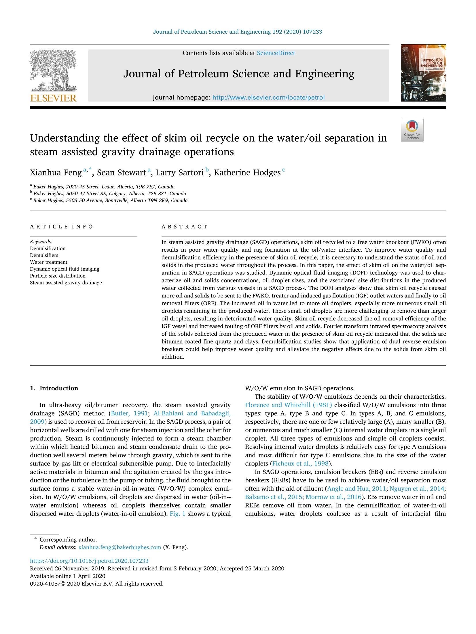
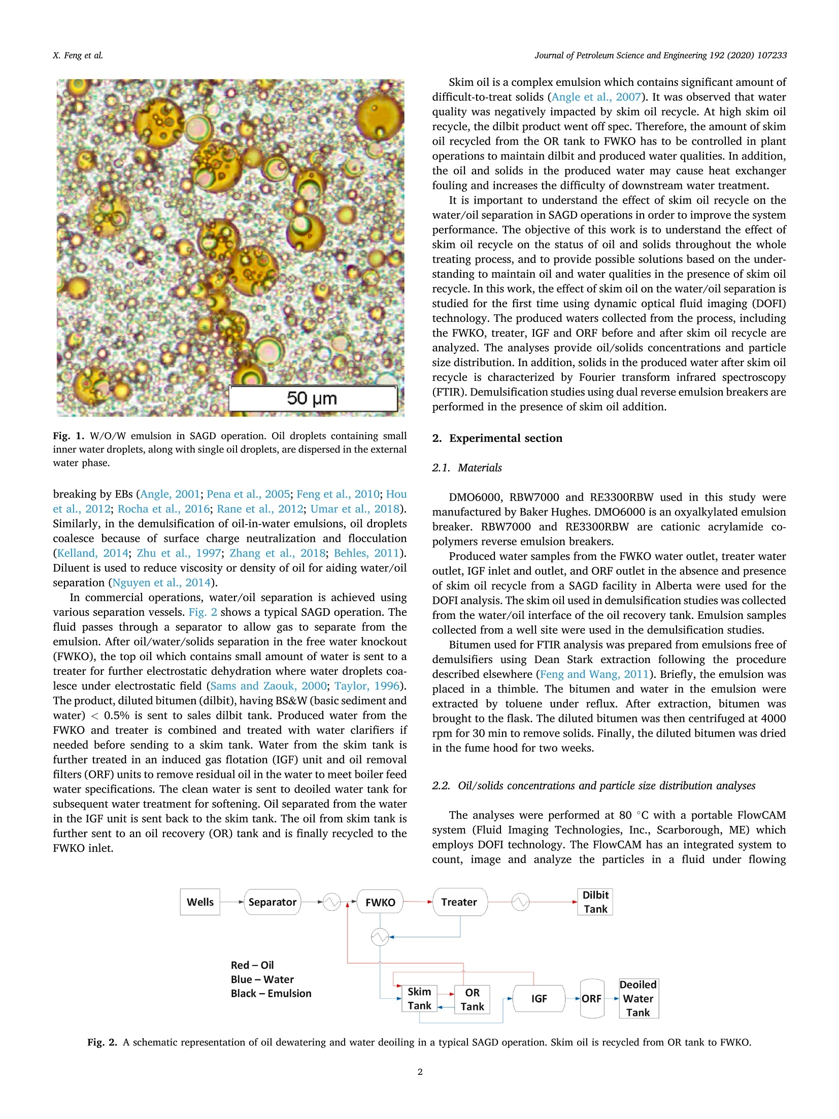
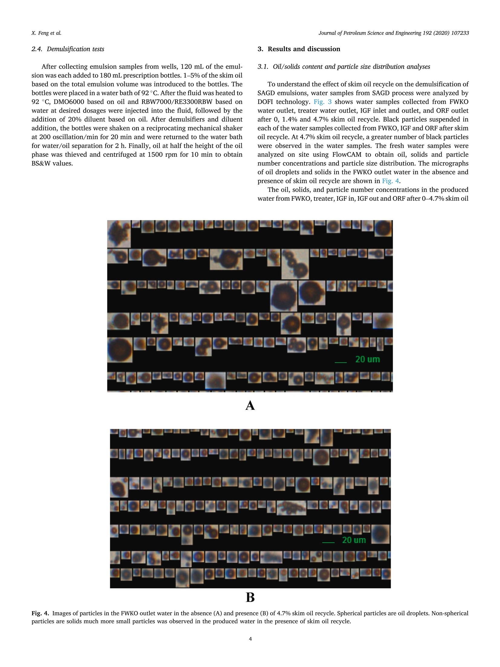
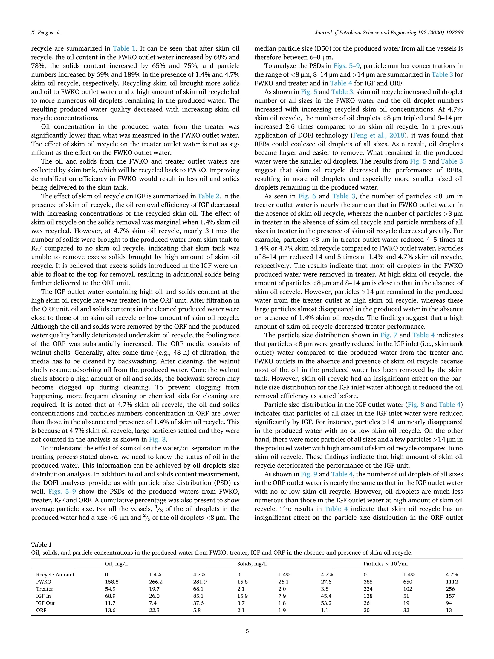
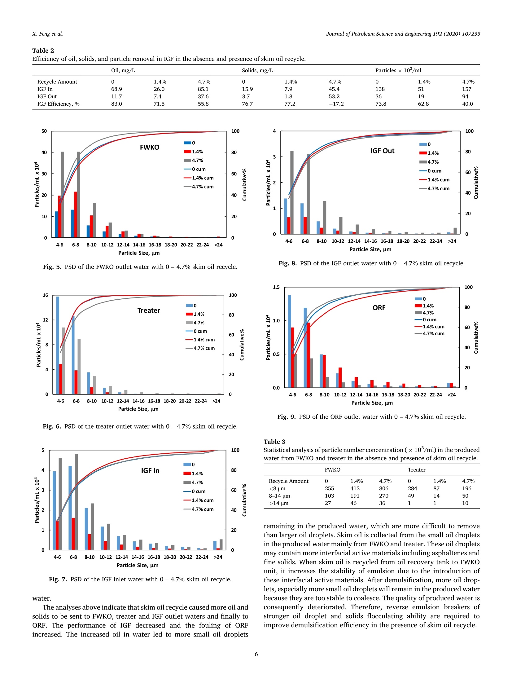
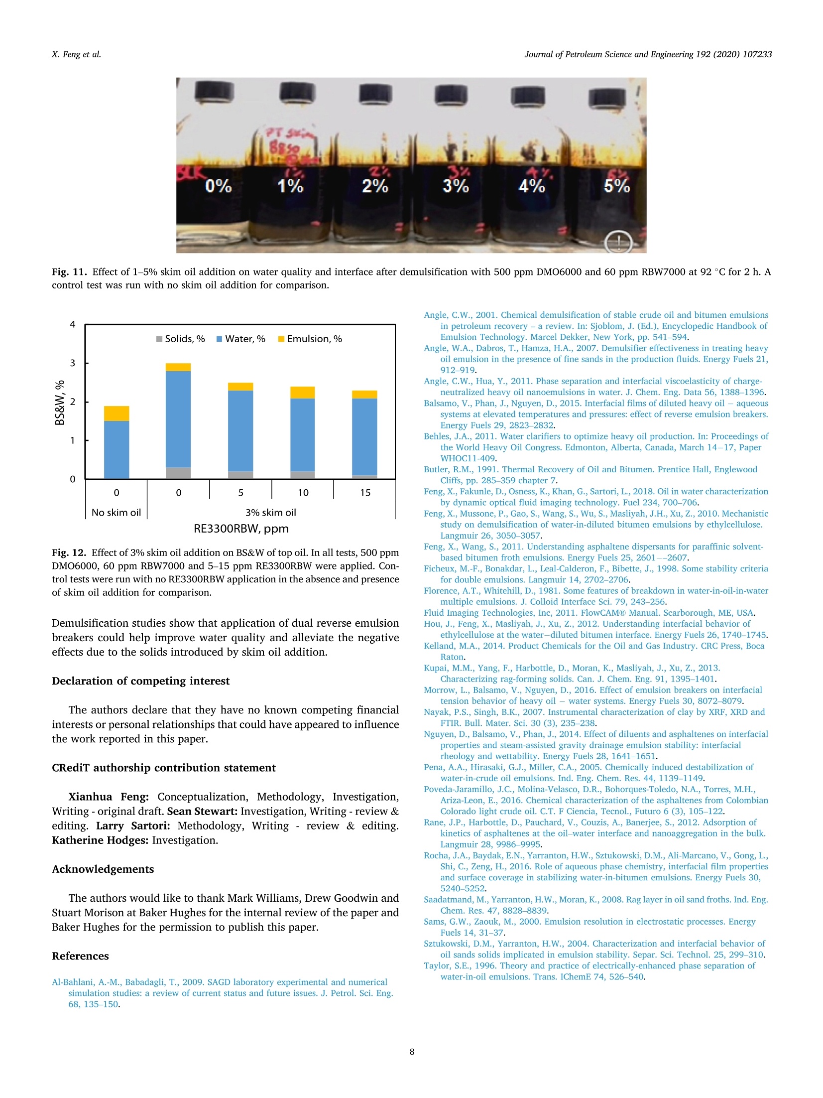
Journal of Petroleum Science and Engineering 192 (2020) 107233Journal of Petroleum Science and Engineering Journal of Petroleum Science and Engineering 192 (2020) 107233X. Feng et al. Contents lists available at ScienceDirect journal homepage: http://www.elsevier.com/locate/petrol Understanding the effect of skim oil recycle on the water/oil separation insteam assisted gravity drainage operations Xianhua Fenga,*,Sean Stewart, Larry Sartori, Katherine HodgesC Baker Hughes, 7020 45 Street, Leduc, Alberta, T9E 7E7, Canada Baker Hughes, 5050 47 Street SE, Calgary, Alberta, T2B 3S1, Canada Baker Hughes, 5503 50 Avenue, Bonnyville, Alberta T9N 2K9, Canada ARTICLEINFO ABSTRACT Keywords: In steam assisted gravity drainage (SAGD) operations, skim oil recycled to a free water knockout (FWKO) oftenDemulsification results in poor water quality and rag formation at the oil/water interface. To improve water quality andDemulsifiers demulsification efficiency in the presence of skim oil recycle, it is necessary to understand the status of oil andWater treatment solids in the produced water throughout the Dprocess. In this paperynamic optica, the effect of skim ol fluid imagiil on the water/oil sengp-Particle size distributionaration in SAGD operations was studied. Dynamic optical fluid imaging (DOFI) technology was used to char-Steam assisted gravity drainageacterize oil and solids concentrations, oil droplet sizes, and the associated size distributions in the producedwater collected from various vessels in a SAGD process. The DOFI analyses show that skim oil recycle causedmore oil and solids to be sent to the FWKO, treater and induced gas flotation (IGF) outlet waters and finally to oilremoval filters (ORF). The increased oil in water led to more oil droplets, especially more numerous small oildroplets remaining in the produced water. These small oil droplets are more challenging to remove than largeroil droplets, resulting in deteriorated water quality. Skim oil recycle decreased the oil removal efficiency of theIGF vessel and increased fouling of ORF filters by oil and solids. Fourier transform infrared spectroscopy analysisof the solids collected from the produced water in the presence of skim oil recycle indicated that the solids arebitumen-coated fine quartz and clays. Demulsification studies show that application of dual reverse emulsionbreakers could help improve water quality and alleviate the negative effects due to the solids from skim oiladdition. 1. Introduction In ultra-heavy oil/bitumen recovery, the steam assisted gravitydrainage (SAGD) method (Butler, 1991; Al-Bahlani and Babadagli,2009) is used to recover oil from reservoir. In the SAGD process,a pair ofhorizontal wells are drilled with one for steam injection and the other forproduction. Steam is continuously injected to form a steam chamberwithin which heated bitumen and steam condensate drain to the pro-duction well several meters below through gravity, which is sent to thesurface by gas lift or electrical submersible pump. Due to interfaciallyactive materials in bitumen and the agitation created by the gas intro-duction or the turbulence in the pump or tubing, the fluid brought to thesurface forms a stable water-in-oil-in-water (W/O/W) complex emul-sion. In W/O/W emulsions, oil droplets are dispersed in water (oil-in--water emulsion) whereas oil droplets themselves contain smallerdispersed water droplets (water-in-oil emulsion). Fig. 1 shows a typical W/O/W emulsion in SAGD operations. The stability of W/O/W emulsions depends on their characteristics.Florence and Whitehill (1981) classified W/O/W emulsions into threetypes: type A, type B and type C. In types A, B, and C emulsions,respectively, there are one or few relatively large (A), many smaller (B),or numerous and much smaller (C) internal water droplets in a single oildroplet. All three types of emulsions and simple oil droplets coexist.Resolving internal water droplets is relatively easy for type A emulsionsand most difficult for type C emulsions due to the size of the waterdroplets (Ficheux et al., 1998). In SAGD operations, emulsion breakers (EBs) and reverse emulsionbreakers (REBs) have to be used to achieve water/oil separation mostoften with the aid of diluent (Angle and Hua, 2011;Nguyen et al., 2014;Balsamo et al., 2015; Morrow et al., 2016). EBs remove water in oil andREBs remove oil from water. In the demulsification of water-in-oilemulsions, water droplets coalesce as a result of interfacial film ( E-mail address: xianhua.f e ng@bakerhughes.com ( X . Fe n g). ) ( h ttps: // doi . org/10.1016/ j .petrol.2020.107233 ) ( Received 26 November 20 1 9; Re c eived in re v ised form 3 February 20 2 0; Ac c epted 25 March 2020Available online 1 April 2020 ) ( 0920-4105/C 2020 Els e vier B.V. All ri g hts reserved. ) Fig. 1. W/O/W emulsion in SAGD operation. Oil droplets containing smallinner water droplets, along with single oil droplets, are dispersed in the externalwater phase. breaking by EBs (Angle, 2001; Pena et al., 2005; Fenget al., 2010; Houet al., 2012; Rocha et al., 2016; Rane et al., 2012; Umar et al., 2018).Similarly, in the demulsification of oil-in-water emulsions, oil dropletscoalesce because of surface charge neutralization and flocculation(Kelland, 2014; Zhu et al., 1997; Zhang et al., 2018; Behles, 2011).Diluent is used to reduce viscosity or density of oil for aiding water/oilseparation (Nguyen et al., 2014). In commercial operations, water/oil separation is achieved usingvarious separation vessels. Fig. 2 shows a typical SAGD operation. Thefluid passes through a separator to allow gas to separate from theemulsion. After oil/water/solids separation in the free water knockout(FWKO), the top oil which contains small amount of water is sent to atreater for further electrostatic dehydration where water droplets coa-lesce under electrostatic field (Sams and Zaouk, 2000; Taylor, 1996).The product, diluted bitumen (dilbit), having BS&W (basic sediment andwater)< 0.5% is sent to sales dilbit tank. Produced water from theFWKO and treater is combined and treated with water clarifiers ifneeded before sending to a skim tank. Water from the skim tank isfurther treated in an induced gas flotation (IGF) unit and oil removalfilters (ORF) units to remove residual oil in the water to meet boiler feedwater specifications. The clean water is sent to deoiled water tank forsubsequent water treatment for softening. Oil separated from the waterin the IGF unit is sent back to the skim tank. The oil from skim tank isfurther sent to an oil recovery (OR) tank and is finally recycled to theFWKO inlet. Skim oil is a complex emulsion which contains significant amount ofdifficult-to-treat solids (Angle et al., 2007). It was observed that waterquality was negatively impacted by skim oil recycle. At high skim oilrecycle, the dilbit product went off spec. Therefore, the amount of skimoil recycled from the OR tank to FWKO has to be controlled in plantoperations to maintain dilbit and produced water qualities. In addition,the oil and solids in the produced water may cause heat exchangerfouling and increases the difficulty of downstream water treatment. It is important to understand the effect of skim oil recycle on thewater/oil separation in SAGD operations in order to improve the systemperformance. The objective of this work is to understand the effect ofskim oil recycle on the status of oil and solids throughout the wholetreating process, and to provide possible solutions based on the under-standing to maintain oil and water qualities in the presence of skim oilrecycle. In this work, the effect of skim oil on the water/oil separation isstudied for the first time using dynamic optical fluid imaging (DOFI)technology. The produced waters collected from the process, includingthe FWKO, treater, IGF and ORF before and after skim oil recycle areanalyzed. The analyses provide oil/solids concentrations and particlesize distribution. In addition, solids in the produced water after skim oilrecycle is characterized by Fourier transform infrared spectroscopy(FTIR). Demulsification studies using dual reverse emulsion breakers areperformed in the presence of skim oil addition. 2. Experimental section 2.1. Materials DMO6000, RBW7000 and RE3300RBW used in this study weremanufactured by Baker Hughes. DMO6000 is an oxyalkylated emulsionbreaker. RBW7000 and RE3300RBW are cationic acrylamide co-polymers reverse emulsion breakers. Produced water samples from the FWKO water outlet, treater wateroutlet, IGF inlet and outlet, and ORF outlet in the absence and presenceof skim oil recycle from a SAGD facility in Alberta were used for theDOFI analysis. The skim oil used in demulsification studies was collectedfrom the water/oil interface of the oil recovery tank. Emulsion samplescollected from a well site were used in the demulsification studies. Bitumen used for FTIR analysis was prepared from emulsions free ofdemulsifiers using Dean Stark extraction following the proceduredescribed elsewhere (Feng and Wang, 2011). Briefly, the emulsion wasplaced in a thimble. The bitumen and water in the emulsion wereextracted by toluene under reflux. After extraction, bitumen wasbrought to the flask. The diluted bitumen was then centrifuged at 4000rpm for 30 min to remove solids. Finally, the diluted bitumen was driedin the fume hood for two weeks. 2.2. Oil/solids concentrations and particle size distribution analyses The analyses were performed at 80 °C with a portable FlowCAMsystem (Fluid Imaging Technologies, Inc., Scarborough, ME) whichemploys DOFI technology. The FlowCAM has an integrated system tocount, image and analyze the particles in a fluid under flowing condition. Details can be found elsewhere (Fluid Imaging Technologies,2011; Feng et al., 2018). The measurement was performed under thefollowing conditions. One 2 mm (wide)×100 um (thick) flow cell and a10 x magnification objective were installed with the FlowCAM whichallows particles <100 um to be measured. 3 mL water sample was usedin each analysis with the flow rate of water samples being controlled at1 mL/min and photographs were taken at 20 frames/second. 2.3. Solids characterization To collect solids for the analysis, produced water was centrifuged at1000 rpm for 10 min. The precipitated solids was then collected anddried in an oven at 110°C. After drying, the solids was characterized byPerkinElmer Spectrum 100 Fourier transform infrared spectroscopy. (A) (B) (C) 2.4. Demulsification tests After collecting emulsion samples from wells, 120 mL of the emul-sion was each added to 180 mL prescription bottles. 1-5% of the skim oilbased on the total emulsion volume was introduced to the bottles. Thebottles were placed in a water bath of 92°C. After the fluid was heated to92°C, DMO6000 based on oil and RBW7000/RE3300RBW based onwater at desired dosages were injected into the fluid, followed by theaddition of 20% diluent based on oil. After demulsifiers and diluentaddition, the bottles were shaken on a reciprocating mechanical shakerat 200 oscillation/min for 20 min and were returned to the water bathfor water/oil separation for 2 h. Finally, oil at half the height of the oilphase was thieved and centrifuged at 1500 rpm for 10 min to obtainBS&W values. 3. Results and discussion 3.1. Oil/solids content and particle size distribution analyses To understand the effect of skim oil recycle on the demulsification ofSAGD emulsions, water samples from SAGD process were analyzed byDOFI technology. Fig. 3 shows water samples collected from FWKOwater outlet,treater water outlet, IGF inlet and outlet, and ORF outletafter 0, 1.4% and 4.7% skim oil recycle. Black particles suspended ineach of the water samples collected from FWKO, IGF and ORF after skimoil recycle. At 4.7% skim oil recycle, a greater number of black particleswere observed in the water samples. The fresh water samples wereanalyzed on site using FlowCAM to obtain oil, solids and particlenumber concentrations and particle size distribution. The micrographsof oil droplets and solids in the FWKO outlet water in the absence andpresence of skim oil recycle are shown in Fig. 4. The oil, solids, and particle number concentrations in the producedwater from FWKO, treater,IGF in, IGF out and ORF after 0-4.7%skim oil A B recycle are summarized in Table 1. It can be seen that after skim oilrecycle, the oil content in the FWKO outlet water increased by 68% and78%, the solids content increased by 65% and 75%, and particlenumbers increased by 69% and 189% in the presence of 1.4% and 4.7%skim oil recycle, respectively. Recycling skim oil brought more solidsand oil to FWKO outlet water and a high amount of skim oil recycle ledto more numerous oil droplets remaining in the produced water. Theresulting produced water quality decreased with increasing skim oilrecycle concentrations. Oil concentration in the produced water from the treater wassignificantly lower than what was measured in the FWKO outlet water.The effect of skim oil recycle on the treater outlet water is not as sig-nificant as the effect on the FWKO outlet water. The oil and solids from the FWKO and treater outlet waters arecollected by skim tank, which will be recycled back to FWKO. Improvingdemulsification efficiency in FWKO would result in less oil and solidsbeing delivered to the skim tank. The effect of skim oil recycle on IGF is summarized in Table 2. In thepresence of skim oil recycle, the oil removal efficiency of IGF decreasedwith increasing concentrations of the recycled skim oil. The effect ofskim oil recycle on the solids removal was marginal when 1.4% skim oilwas recycled. However, at 4.7% skim oil recycle, nearly 3 times thenumber of solids were brought to the produced water from skim tank toIGF compared to no skim oil recycle, indicating that skim tank wasunable to remove excess solids brought by high amount of skim oilrecycle. It is believed that excess solids introduced in the IGF were un-able to float to the top for removal, resulting in additional solids beingfurther delivered to the ORF unit. The IGF outlet water containing high oil and solids content at thehigh skim oil recycle rate was treated in the ORF unit. After filtration inthe ORF unit, oil and solids contents in the cleaned produced water wereclose to those of no skim oil recycle or low amount of skim oil recycle.Although the oil and solids were removed by the ORF and the producedwater quality hardly deteriorated under skim oil recycle, the fouling rateof the ORF was substantially increased. The ORF media consists ofwalnut shells. Generally, after some time (e.g., 48 h) of filtration, themedia has to be cleaned by backwashing.After cleaning, the walnutshells resume adsorbing oil from the produced water. Once the walnutshells absorb a high amount of oil and solids, the backwash screen maybecome clogged up during cleaning. To prevent clogging fromhappening, more frequent cleaning or chemical aids for cleaning arerequired. It is noted that at 4.7% skim oil recycle, the oil and solidsconcentrations and particles numbers concentration in ORF are lowerthan those in the absence and presence of 1.4% of skim oil recycle. Thisis because at 4.7% skim oil recycle, large particles settled and they werenot counted in the analysis as shown in Fig. 3. To understand the effect of skim oil on the water/oil separation in thetreating process stated above, we need to know the status of oil in theproduced water. This information can be achieved by oil droplets sizedistribution analysis. In addition to oil and solids content measurement,the DOFI analyses provide us with particle size distribution (PSD) aswell. Figs. 5-9 show the PSDs of the produced waters from FWKO,treater, IGF and ORF. A cumulative percentage was also present to showaverage particle size. For all the vessels, /s of the oil droplets in theproduced water had a size <6 um and "/3 of the oil droplets <8 um. The median particle size (D50) for the produced water from all the vessels istherefore between 6-8 um. As seen in Fig. 6 and Table 3, the number of particles <8 um intreater outlet water is nearly the same as that in FWKO outlet water inthe absence of skim oil recycle, whereas the number of particles >8 umin treater in the absence of skim oil recycle and particle numbers of allsizes in treater in the presence of skim oil recycle decreased greatly. Forexample, particles <8 um in treater outlet water reduced 4-5 times at1.4% or 4.7% skim oil recycle compared to FWKO outlet water. Particlesof 8-14 um reduced 14 and 5 times at 1.4% and 4.7% skim oil recycle,respectively. The results indicate that most oil droplets in the FWKOproduced water were removed in treater. At high skim oil recycle, theamount of particles <8 um and 8-14 um is close to that in the absence ofskim oil recycle. However, particles >14 um remained in the producedwater from the treater outlet at high skim oil recycle, whereas theselarge particles almost disappeared in the produced water in the absenceor presence of 1.4% skim oil recycle. The findings suggest that a highamount of skim oil recycle decreased treater performance. The particle size distribution shown in Fig. 7 and Table 4 indicatesthat particles <8 um were greatly reduced in the IGF inlet (i.e., skim tankoutlet) water compared to the produced water from the treater andFWKO outlets in the absence and presence of skim oil recycle becausemost of the oil in the produced water has been removed by the skimtank. However, skim oil recycle had an insignificant effect on the par-ticle size distribution for the IGF inlet water although it reduced the oilremoval efficiency as stated before. Particle size distribution in the IGF outlet water (Fig.8 and Table 4)indicates that particles of all sizes in the IGF inlet water were reducedsignificantly by IGF. For instance, particles >14 um nearly disappearedin the produced water with no or low skim oil recycle. On the otherhand, there were more particles of all sizes and a few particles >14 um inthe produced water with high amount of skim oil recycle compared to noskim oil recycle. These findings indicate that high amount of skim oilrecycle deteriorated the performance of the IGF unit. As shown in Fig. 9 and Table 4, the number of oil droplets of all sizesin the ORF outlet water is nearly the same as that in the IGF outlet waterwith no or low skim oil recycle. However, oil droplets are much lessnumerous than those in the IGF outlet water at high amount of skim oilrecycle. The results in Table 4 indicate that skim oil recycle has aninsignificant effect on the particle size distribution in the ORF outlet Table 1 Oil, solids, and particle concentrations in the produced water from FWKO, treater, IGF and ORF in the absence and presence of skim oil recycle. Oil, mg/L Solids, mg/L Particles x 10’/ml Recycle Amount 0 1.4% 4.7% 0 1.4% 4.7% 0 1.4% 4.7% FWKO 158.8 266.2 281.9 15.8 26.1 27.6 385 650 1112 Treater 54.9 19.7 68.1 2.1 2.0 3.8 334 102 256 IGF In 68.9 26.0 85.1 15.9 7.9 45.4 138 51 157 IGF Out 11.7 7.4 37.6 3.7 1.8 53.2 36 19 94 ORF 13.6 22.3 5.8 2.1 1.9 1.1 30 32 13 Table 2Efficiency of oil, solids, and particle removal in IGF in the absence and presence of skim oil recycle. Oil, mg/L Solids, mg/L Particles x 10/ml Recycle Amount 0 1.4% 4.7% 0 1.4% 4.7% 0 1.4% 4.7% IGF In 68.9 26.0 85.1 15.9 7.9 45.4 138 51 157 IGF Out 11.7 7.4 37.6 3.7 1.8 53.2 36 19 94 IGF Efficiency,% 83.0 71.5 55.8 76.7 77.2 -17.2 73.8 62.8 40.0 : Fig. 8. PSD of the IGF outlet water with 0 - 4.7% skim oil recycle. Fig. 5. PSD of the FWKO outlet water with 0 -4.7% skim oil recycle. 3 Fig. 9. PSD of the ORF outlet water with 0 - 4.7% skim oil recycle. Fig. 6. PSD of the treater outlet water with 0 -4.7% skim oil recycle. Table 3 Statistical analysis of particle number concentration (×10/ml) in the producedwater from FWKO and treater in the absence and presence of skim oil recycle. 3 FWKO Treater Recycle Amount 0 1.4% 4.7% 0 1.4% 4.7% <8 um 255 413 806 284 196 8-14 pm 103 270 49 >14 um 27 36 1 1 Fig. 7. PSD of the IGF inlet water with 0-4.7% skim oil recycle. water. The analyses above indicate that skim oil recycle caused more oil andsolids to be sent to FWKO, treater and IGF outlet waters and finally toORF. The performance of IGF decreased and the fouling of ORFincreased. The increased oil in water led to more small oil droplets remaining in the produced water, which are more difficult to removethan larger oil droplets. Skim oil is collected from the small oil dropletsin the produced water mainly from FWKO and treater. These oil dropletsmay contain more interfacial active materials including asphaltenes andfine solids. When skim oil is recycled from oil recovery tank to FWKOunit, it increases the stability of emulsion due to the introduction ofthese interfacial active materials. After demulsification, more oil drop-lets, especially more small oil droplets will remain in the produced waterbecause they are too stable to coalesce. The quality of produced water isconsequently deteriorated. Therefore, reverse emulsion breakers ofstronger oil droplet and solids flocculating ability are required toimprove demulsification efficiency in the presence of skim oil recycle. IGF In IGF Out ORF Recycle Amount 0 1.4% 4.7% 0 1.4% 4.7% 0 1.4% 4.7% <8 pm 81 31 94 26 13 63 20 19 9 8-14 pm 39 15 44 8 4 23 8 9 3 >14 um 18 5 19 2 2 8 2 4 1 It was observed that skim oil recycle brought solids into the producedwater. As shown in Fig. 3, suspended black particles was observed in theproduced waters from FWKO, IGF inlet and outlet, and ORF after skimoil recycle. However, black particles were observed neither in the pro-duced waters from treater with and without skim oil recycle, nor in thewater from all vessels in the absence of skim oil recycle. To understandthe effect of such solids on the water/oil separation, it is necessary toknow the characteristics of the solids. Fig. 10 displays the FTIR spectra of all solids along with the spectrumof bitumen for comparison. The assignment of bands are as follows(Poveda-Jaramillo et al., 2016; Nayak and Singh,2007). The bands at2900 cm-, 2850 cm-,1650 cm-1,1455 cm-, 1377 cm-,810 cm-and 747 cm-l are due to stretching, bending and deformation vibrationsof CH. The band at 1030 cmis due to the stretching vibration of etherlinkage. The broad bands at 3200 cm-and 1100 cm-are OH andSi-O-Si stretching vibrations, respectively. The band at 1100 cm-l canbe ascribed to quartz (SiO2). The bands at 3200 cm-and1100 cm- canbe assigned to kaolinite (Al2Si2Os(OH)4). The comparison of the FTIRfeatures of solids and bitumen reveals that the solids are quartz andkaolinite (clay) which are coated with bitumen. The bitumen coated finesolids make emulsions harder to break because they stabilize theemulsions by absorbing at the oil/water interface (Sztukowski andYarranton, 2004). The solids are sent to the skim tank with the producedwater. To remove the solids in the produced water, prior to beingrecycled back to FWKO, the skim oil can be pretreated by demulsifierswhich are able to change the wettability of fine solids and drop the solidsto the sand slurry at the bottom of FWKO. Alternately, the skim oil canbe treated along with the emulsion in FWKO using emulsion breakers ofstrong solids removal ability. It must be pointed out that the bitumen coated on the solids was notcounted in the oil concentration in the produced water analysis by theDOFI technology. In traditional oil in water analysis, oil is firstlyextracted by toluene or other solvent, and the oil concentration ismeasured by a turbidity meter or UV-vis spectrophotometer (Zhanget al., 2018). In this case, the oil coated on the solids, although very Fig. 10. FTIR spectra of the solids collected from FWKO, IGF in, IGF out andORF water samples after 4.7% skim oil recycle. The bitumen spectrum is shownfor comparison. 3.3. Effect of skim oil on water/oil separation As stated before, more efficient EB and REB are required to improveoil/water/solids separation in the presence of skim oil recycle. Since themost significant negative effect is in FWKO which is the main vessel foroil/water/solids separation, we can use regular bottle tests to simulatedemulsification in FWKO to explore possible solutions. Demulsification tests were performed using 500 ppm DMO6000 and60 ppm RBW7000 with fresh emulsion and 0-5% skim oil addition.Fig.11 shows the water- oil separation after demulsification at 92 °C for2 h. It is observed that the separated water was relatively clean in theabsence of skim oil addition, whereas water quality deteriorated withincreasing the amount of skim oil addition. The water/oil interface wasstraight and even in the absence of skim oil addition. However, theinterface became very uneven (i.e., raggy) in the presence of skim oiladdition and the raggy interface expanded with more skim oil addition.The resulting rag layer at the water/oil interface is a mixture of unre-solved emulsion and solids (Saadatmand et al., 2008; Kupai et al., 2013).The results suggest that skim oil recycle brought more solids to theemulsion. The solids are bi-wettable, which remains at the water/oilinterface, interfering with water/oil separation and reducing demulsi-fication efficiency. As a result, the water quality deteriorated. Thisobservation agrees with the findings from the DOFI analysis statedbefore. To improve water quality and alleviate the negative effects due to thesolids from skim oil addition, a second REB, i.e., RE3300RBW wasapplied along with the incumbent DMO6000 and RBW7000 to treat theemulsion with skim oil added. Fig. 12 shows the BS&W of the top oilafter demulsification at 92 °C for 2 h. Without added skim oil, there wasnearly no solids in the top oil after demulsification even if no second REBwas used. When 3% skim oil was added to the emulsion, there was 0.3%solids remaining in the top oil if no secondary REB was applied in thedemulsification. Moreover, the total BS&W increased 60% compared tono skim oil addition. The application of a second REB reduced the solidsin the top oil, but did not remove the solids completely. For example,theapplication of 15 ppm s REB reduced BS&W by 80% compared to nosecond REB being applied when 3% skim oil was added. In addition, itwas observed that water quality improved in the application of thesecond REB. The results show that the application of dual REBs couldhelp alleviate the negative effects of skim oil addition by improvingwater quality and reducing solids content. 4. Conclusions Skim oil recycled to FWKO results in poor water quality and ragformation at the water/oil interface. The dynamic optical fluid imaginganalyses for the produced water collected from various vessels in theSAGD process show that skim oil recycle caused more oil and solids to besent to FWKO, treater and IGF outlet waters and finally to ORF. Theincreased oil in water led to more small oil droplets remaining in theproduced water, which is harder to remove than larger oil droplets. Skimoil recycle decreased the oil removal efficiency of the IGF vessel andincreased fouling of ORF filters. FTIR analysis of the solids suspended inthe water samples from FWKO, IGF, and ORF after skim oil recycle in-dicates that the solids are bitumen-coated fine quartz and clays. Fig. 12. Effect of 3% skim oil addition on BS&W of top oil. In all tests, 500 ppmDMO6000, 60 ppm RBW7000 and 5-15 ppm RE3300RBW were applied. Con-trol tests were run with no RE3300RBW application in the absence and presenceof skim oil addition for comparison. Demulsification studies show that application of dual reverse emulsionbreakers could help improve water quality and alleviate the negativeeffects due to the solids introduced by skim oil addition. Declaration of competing interest The authors declare that they have no known competing financialinterests or personal relationships that could have appeared to influencethe work reported in this paper. CRediT authorship contribution statement Xianhua Feng: Conceptualization, Methodology, Investigation,Writing-original draft. Sean Stewart: Investigation, Writing- review &editing. Larry Sartori: Methodology, Writing - review & editing.Katherine Hodges: Investigation. Acknowledgements The authors would like to thank Mark Williams, Drew Goodwin andStuart Morison at Baker Hughes for the internal review of the paper andBaker Hughes for the permission to publish this paper. References Angle, C.W., 2001. Chemical demulsification of stable crude oil and bitumen emulsionsin petroleum recovery - a review. In:Sjoblom, J. (Ed.), Encyclopedic Handbook ofEmulsion Technology. Marcel Dekker, New York, pp. 541-594. Angle, W.A., Dabros, T., Hamza, H.A., 2007. Demulsifier effectiveness in treating heavyoil emulsion in the presence of fine sands in the production fluids. Energy Fuels 21,912-919. Angle, C.W., Hua, Y., 2011. Phase separation and interfacial viscoelasticity of charge-neutralized heavy oil nanoemulsions in water. J. Chem. Eng. Data 56, 1388-1396. Balsamo, V., Phan, J., Nguyen, D., 2015. Interfacial films of diluted heavy oil - aqueoussystems at elevated temperatures and pressures: effect of reverse emulsion breakers.Energy Fuels 29,2823-2832. Behles, J.A., 2011. Water clarifiers to optimize heavy oil production. In: Proceedings ofthe World Heavy Oil Congress. Edmonton, Alberta, Canada, March 14-17, PaperWHOC11-409. Butler, R.M., 1991. Thermal Recovery of Oil and Bitumen. Prentice Hall,EnglewoodCliffs, pp. 285-359 chapter 7. Feng,X., Fakunle, D., Osness, K., Khan, G., Sartori, L., 2018. Oil in water characterizationby dynamic optical fluid imaging technology. Fuel 234, 700-706. Feng,X., Mussone,P., Gao, S., Wang, S., Wu,S., Masliyah, J.H., Xu, Z., 2010. Mechanisticstudy on demulsification of water-in-diluted bitumen emulsions by ethylcellulose.Langmuir 26, 3050-3057. Feng, X., Wang, S., 2011.Understanding asphaltene dispersants for paraffinic solvent-based bitumen froth emulsions. Energy Fuels 25, 2601--2607. Ficheux, M.-F., Bonakdar, L., Leal-Calderon, F.,Bibette,J., 1998. Some stability criteriafor double emulsions. Langmuir 14,2702-2706. Florence, A.T., Whitehill, D., 1981. Some features of breakdown in water-in-oil-in-watermultiple emulsions. J. Colloid Interface Sci. 79, 243-256. Fluid Imaging Technologies, Inc, 2011. FlowCAMQ Manual. Scarborough, ME, USA.Hou, J., Feng, X., Masliyah, J., Xu, Z., 2012. Understanding interfacial behavior of ethylcellulose at the water-diluted bitumen interface. Energy Fuels 26, 1740-1745. Kelland, M.A., 2014. Product Chemicals for the Oil and Gas Industry. CRC Press, BocaRaton. Kupai, M.M., Yang, F., Harbottle, D., Moran, K., Masliyah, J., Xu, Z., 2013.Characterizing rag-forming solids. Can. J. Chem. Eng.91,1395-1401. Morrow, L., Balsamo, V., Nguyen, D., 2016. Effect of emulsion breakers on interfacialtension behavior of heavy oil - water systems. Energy Fuels 30, 8072-8079. Nayak, P.S., Singh, B.K., 2007. Instrumental characterization of clay by XRF, XRD andFTIR. Bull. Mater. Sci. 30 (3), 235-238. Nguyen, D., Balsamo, V., Phan, J., 2014. Effect of diluents and asphaltenes on interfacialproperties and steam-assisted gravity drainage emulsion stability: interfacialrheology and wettability. Energy Fuels 28, 1641-1651. Pena, A.A., Hirasaki, G.J., Miller, C.A., 2005. Chemically induced destabilization ofwater-in-crude oil emulsions. Ind. Eng. Chem. Res. 44, 1139-1149. Poveda-Jaramillo, J.C.,Molina-Velasco, D.R., Bohorques-Toledo, N.A., Torres, M.H.,Ariza-Leon, E., 2016. Chemical characterization of the asphaltenes from ColombianColorado light crude oil. C.T. F Ciencia, Tecnol., Futuro 6(3), 105-122. Rane, J.P., Harbottle, D., Pauchard, V., Couzis, A., Banerjee, S., 2012. Adsorption ofkinetics of asphaltenes at the oil-water interface and nanoaggregation in the bulk.Langmuir 28, 9986-9995. Rocha,J.A., Baydak, E.N., Yarranton, H.W., Sztukowski, D.M., Ali-Marcano, V., Gong, L.,Shi, C., Zeng, H., 2016. Role of aqueous phase chemistry, interfacial film propertiesand surface coverage in stabilizing water-in-bitumen emulsions. Energy Fuels 30,5240-5252. Saadatmand, M., Yarranton, H.W., Moran, K., 2008. Rag layer in oil sand froths. Ind.Eng.Chem. Res. 47, 8828-8839. Sams, G.W., Zaouk, M., 2000. Emulsion resolution in electrostatic processes. EnergyFuels 14, 31-37. Sztukowski, D.M., Yarranton, H.W., 2004. Characterization and interfacial behavior ofoil sands solids implicated in emulsion stability. Separ. Sci. Technol. 25, 299-310. Taylor, S.E., 1996. Theory and practice of electrically-enhanced phase separation ofwater-in-oil emulsions. Trans. IChemE 74, 526-540. 在蒸汽辅助重力排水(SAGD)作业中,脱脂油回收至游离水分离器(FWKO),往往会导致油水界面水质差和碎屑形成。为了在脱脂油回收的情况下提高水质和破乳效率,有必要了解整个过程中采出水中的油和固体的状态。本文研究了脱脂油对SAGD操作中水/油分离的影响。采用动流式颗粒成像(DOFI)技术,对SAGD工艺从不同容器中收集的采出水中的油和固体浓度、油滴大小以及相关的粒径分布进行了表征。DOFI分析表明,脱脂油的再循环导致更多的油和固体被输送到FWKO、处理器和诱导气浮(IGF)出口水域,最终进入去油过滤器(ORF)。水中含油量的增加导致油滴增多,尤其是在采出水中残留的小油滴增多。这些小油滴比大油滴更难去除,导致水质恶化。脱脂油的循环利用降低了IGF容器的除油效率,增加了ORF过滤器受油和固体颗粒的污染。破乳研究表明,采用双反乳化破乳剂可以改善水质,减轻添加脱脂油后的固体对水质的负面影响。
确定

还剩7页未读,是否继续阅读?

产品配置单


大昌华嘉科学仪器为您提供《蒸汽辅助重力排水作业中脱脂油循环对水/油分离的影响检测方案(图像粒度粒形)》,该方案主要用于其他中理化分析检测,参考标准--,《蒸汽辅助重力排水作业中脱脂油循环对水/油分离的影响检测方案(图像粒度粒形)》用到的仪器有流式颗粒成像分析系统FlowCam®8100、颗粒成像法+光阻法分析系统 FlowCam® + LO、FlowCam® 5000颗粒分析仪
相关方案
更多
该厂商其他方案
更多